10Gbit Intel NICs and pfSense

As 10Gbit is becoming more and more common in large networks to cope with the ever increasing amount of data that is moved between service providers and users I have taken some time to look into what others have done when working with pfSense. I’ve limited my research to systems based on Intel 10Gbit NICs as they’re the most cost effective – high performance at low cost – and I’ve really good experiences with the 1Gbit Intel NICs.

First off the NICs have to be compatible with pfSense which is based on FreeBSD. When looking at [1] Intel provides a driver for the NICs based on the 82598 and 82599 chips, as well as the X540 cards. This indicates that there are some cards out there which provides 10Gbit capabilities for FreeBSD (from FreeBSD 7.3 and above) and therefore also pfSense. However when looking at the available configurations it only possible to get two interfaces in one NIC with multimode fiber or copper, but not with single mode fiber. However when looking at the price of the single mode fiber variations kind of exclude them as they’re twice the price of that copper variations; even with two interfaces. On a final note the Intel 10Gbit NICs all require PCIe 2.0 or higher as a minimum, which excludes a lot of servers that I’ve available, because they are based on the Intel 5000 chipset.

When looking at the pfSense forums there has been several dicussion recently on the Intel NICs, especially the X520 and X540, and from the debate it seems clear that running pfSense straight on hardware doesn’t work well with pfSense 2.1.x, there is a problem with the MBUF of the driver for the NICs [2]. A solution proposed to solve problem is to use VMware ESXi to hypervise the hardware and “mask” the NICs as VXNET3 interfaces and then install pfSense on top of that. A guide to do this can be found in [3]. The writer of the guide reports that transfering 7Gbit of traffic distributed over 132 VLANs and ~160 subnets without any problems [4]. From what I’ve been able to gather from the pfSense forum the MBUF error wouldn’t be corrected in the 2.1.x branch as it’s based on FreeBSD 8.3, but the 2.2 version of pfSense will address this problem as it will be based on FreeBSD 10.0, where the problem with the drivers have been corrected. Unfortunately pfSense 2.2 is only in Alpha at the time of writing and therefore unlikely to reach Stable status before the end of this year.

References
 

NPF#14: Internet bandwidth load

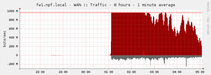
So first let me give you some facts on the load on our internet line at NPF#13, we had an average load of 600Mbps and a peak of just over 1Gbps, which caused some latency spikes saturday evening after the stage show. The number of participants was 1200 people and we had a single pfSense routing the traffic, with a second ready as backup. With these fact in mind and a ticket sale of 2200 for NPF#14, which is a 83% increase from NPF#13, we would expect that 2Gbps on the internet line should be sufficient. More precise my expectation on the load was approximately 1.1Gbps on average and a peak of about 1.8Gbps, but as we’ll see in a bit this was way off the actual measured values.

Luckily we had four 1Gbps lines, well due to time pressure and my underestimation of number of crew (network technicians) needed we only had single line up and running at the time of opening. But my hope was that we in time could get the other lines up and running before the internet bandwidth became a problem. Unfortunately due to other problems with network it wasn’t until 9 o’clock I had time to work on the second gigabit line and by that time the first line was under pressure especially after the stage show and at the start of the tournaments.

First WAN link load

First WAN link load

This unfortunately forced the game admins of League of Legends and Counter Strike: Global Offensive to postpone the tournaments until we had more bandwidth as Riot Games (League of Legends) and Valve (Counter Strike: Global Offensive) had released updates during that evening and people weren’t able to download them fast enough. After spending the better part of 4 hours – with a lot of interruptions – I finally got the second gigabit line up and running. This is where the funny part comes, namely that it took less than 30 seconds before the second line was fully utilized. People luckily did however report that there speedtests on http://speedtest.net/ increased from 0.4Mbps to approximately 25Mbps.

Second WAN link load

Second WAN link load

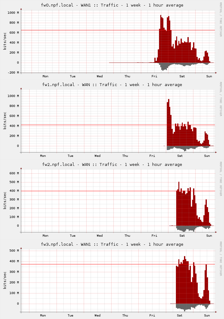
This however didn’t solve the bandwidth problem completely, and I started setting the third and fourth pfSenses up, however with one major difference namely that we, BitNissen and I, found that it’s possible to extract the configuration of one pfSense and load it into another pfSense. All that there were left for us to do was to make some adjustments to the public IP values, this didn’t succeeded in the first attempt because we missed some things which forced us to do some manual troubleshooting to correct the mistakes. We learned from these mistakes and the fourth pfSense was configured in less 10 minuttes. By the time we got to this point it was 4 o’clock in morning and the load on the WAN links had dropped considerably, therefore I decided to get a couple of hours sleep before connecting it to our network, before the tournaments were set start again (saturday 10 o’clock). Around 9:30 the last two pfSenses were connected to our network and from that point on we didn’t have any problem with the internet bandwidth. As mentioned in another blog, NPF#14: Network for 2200 people, we ended up having 23TB of traffic in total on the WAN interfaces of our core switches, and that is in only 47 hours. Below you can see the average load on the four WAN links.

Load on the different WAN links

Load on the different WAN links

Finally I will just mention that we saturday evening measured a bandwidth load peak of 2.8Gbps and on average use just over 2.1-2.2Gbps during normal gaming hours, which was a lot more than originally expected. So I’m guessing next year that we’ll need a 10Gbps or large line in order not to run out of bandwidth, if we choose to expand further.

NPF#14: Network for 2200 people

So let me be the first to acknowl that this year the network course more problems than what is good and much of it properly could have been caught with more preparation. The three main problems where the internet connection, DHCP snooping on the access switches, and the configuration of the SMC switches used as access switches. On that note let me make it clear that the two first problems where solved during the first evening and the last problem wasn’t solved completely only to the best of our ability. The general network worked very well and we didn’t have any problems with our Cisco hardware after friday evening, apart from a single Layer 1 problem – where someone had disconnected the uplink cable to a switch.

The size of network and traffic makes it equivalent to a medium sized company. We have 2200 participants with relative high requirements to bandwidth and not to mention several streamers. This puts so pressure on the distribution and core hardware. A typical construction to obtain highest possible speed is to use what I would call a double star topology. The first star topology is from the core switches/router to the distribution switches and the second star topology is from the distribution switches to the access switches. This is what DreamHack uses with some built-in redundancies. We’ve however chosen a different topology for our network, namely what I would call a loop-star topology. The top topology is a loop where the core and distribution switches/routers are connected in one or more loop(s), and the bottom topology is a star from the distribution switches to the access switches. The top topology does of course places some requirements to the core and distribution in terms of routing protocols, if you choose to use layer 3 between them as we did.

Double star and Loop-star topologies

Double star and Loop-star topologies

The protocol we choose for our layer 3 routing was OSPF, as the original design included some HP ProCurve switches for distribution and EIGRP is Cisco proprietary and those not really an option. One of the remaining possibilities was RIP, but this protocol doesn’t propagate fast enough in a loop topology and those isn’t really an option either. The reason for choosing the loop topology is quite simply redundancy in the distribution layer and the idea of doing it this way is taken from the construction of the network made for SL2012 (Spejdernes Lejr 2012 – http://sl2012.dk/en), where I helped out as a network technician. The major differences from SL2012 to NPF#14 is the number of loops and bandwidth between the distribution points – SL2012 had a single one gigabit loop and two places where the internet was connected to the loop, while we at NPF#14 had two loops, one with two gigabits for administrative purposes and one with four gigabit for the participants, and only a single place where four gigabit internet was connected. Our core consisted of two Cisco switches in stack, each of the participants distribution switches was a 48-port Cisco switch and each of the administrative distribution switches was a 24-port Cisco switch. For the internet we had four 1 gigabit lines which each where setup on a pfSense for NATing on to the different scopes of the internet-lines, and we then used the Cisco layer 3 protocol for load-balancing the four lines. Finally everything from the distribution switches to the access switches is layer 2 based, and this also the way we control the number of people on the same subnet and on the same public IP as we don’t have a public IP per participant.

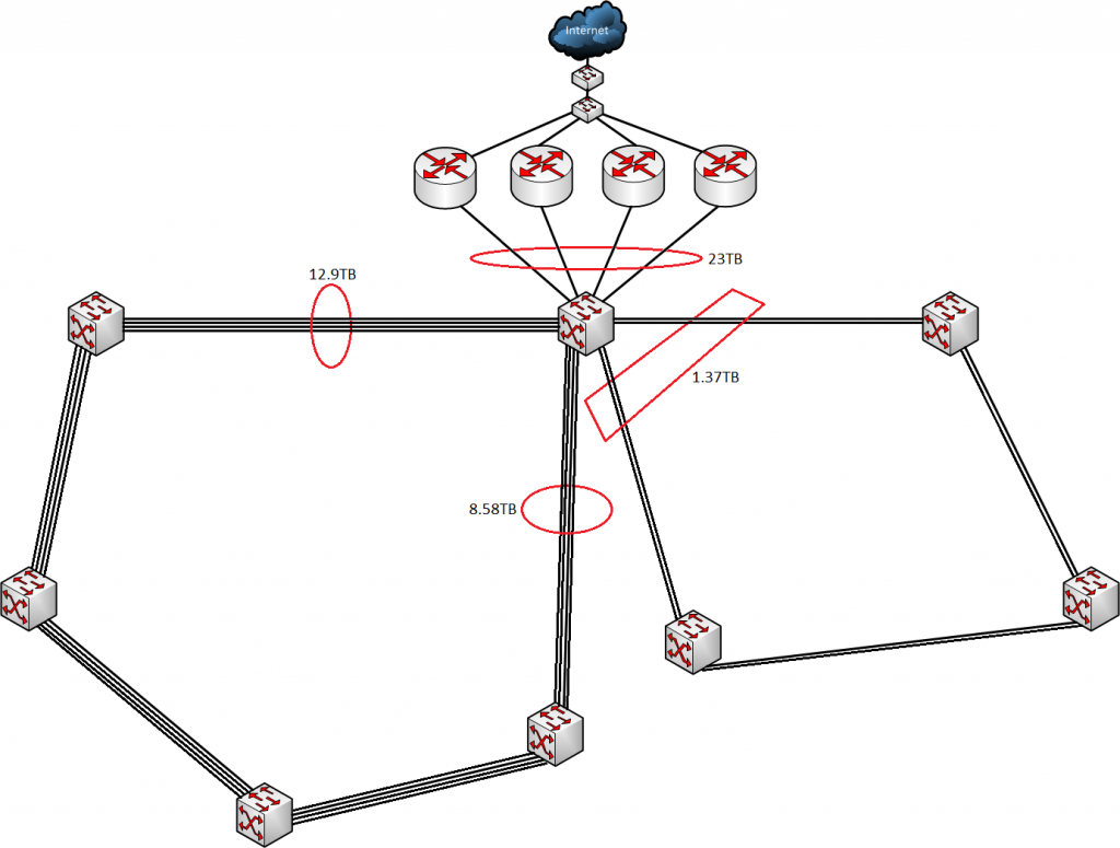
But enough about the construction of our network let us take a look at the traffic amounts over the 47 hours the event lasted. First of the four internet lines moved 23TB of data, of which 20.2TB was download and 2.8TB was upload. The amount of traffic moved through the core on the participant loop was 21.48TB, 12.9TB on one side and 8.58TB on the other side. The administrative loop on the other hand only moved 1.37TB of data through core switch. With a little math we get that the average load on the participant loop respectively is 625Mbps and 415Mbps, while the administrative loop load average is 66.3Mbps. The average load on the internet from the core was 1.114Gbps, with a measured peak of 2.8Gbps. In the picture below the data is placed on the connections between the switches.

Traffic on different interfaces

Traffic on different interfaces

We have learned a thing or two from this year’s construction of network, layer 3 routing between distribution points and a multi-loop topology can work for a LAN Party of our size. Furthermore we might be able to reduce the size of the bandwidth on loops a bit, the average loads are fairly low – but this doesn’t say anything about peak load performance which we encounter friday and saturday evening. Therefore for good measure the bandwidth on the different types of loops should properly just stay the same. Depending on the growth next year it might be a reasonable idea to make two participant distribution loops instead of just one and maintain the bandwidth of 4Gbps on both loops. Also depending on growth the bandwidth on the internet has to follow, we’re fairly close to our limit this year.

End-course project 6

Date: 13th of June 2013
Participating group members: Kenneth Baagøe, Morten D. Bech and Thomas Winding
Activity duration: 4 hours

Discussion
Vision
Our vision for this end-course project was to build a game consisting of a remote controlled robot and a number of autonomous robots as described in End-course project 0 [1].

Achievements
Building and programming the RC robot was the very first achievement in this project. The simple idea of making a remote controlled robot which you control through a first person view, gave a larger amount of immersion than we had expected.

In this project, the autonomous robots are the elements that we’re the most proud of. Making the robots behave as animals searching for food while also trying to protect themselves from the player has been a challenge due to the sensors and the environment. Also the remote controlled robot we find very satisfying due to the expectations of the functionality. The game is fully functional, however, we were not able to achieve some of our envisioned goals. Originally we intended to control the remote controlled robot through an interface on a tablet, but the current implementation has the video feed and the control on a PC instead. The cause of this has been described in an earlier entry [2]: We were unable to achieve an acceptable amount of latency on a video feed implemented in the program for controlling the robot. Instead of implementing the video stream in the remote control program, we used a Skype video call, which had a much more acceptable amount of latency. The result of this was that we needed to have two different programs running simultaneously. Due to time constraints we did not look in to how we would be able to handle this on a tablet device and instead chose to run the Skype call on one machine and the remote control program on another.

Observations and future works
After testing the game, we thought of some changes that could help to improve the game. The first person view gives a realistic and fun aspect to the game, but it also gives some unforeseen complications. When the player robot approaches an autonomous robot, to hit it, the distance between the player robot and the autonomous is very short, which results in the first person view being completely obscured by the autonomous robot. This makes it hard to see if it is actually possible to hit the autonomous robot from where you are. As a result of this, if it is possible, one might find himself looking directly at the arena instead of at the screen displaying the view of the robot, which we did not intend. A reconstruction of the RC vehicle could be one solution to this problem. By placing the camera in a way so as to create a third person view instead of the first person view, could provide a better view of what is going on in the arena during the game, while still providing immersion in the game.

Another improvement to the remote controlled robot would be to add an amount of acceleration as the latency in both video feed and Bluetooth communication meant that, when controlling the robot, you would get jerky movements as it would instantly go full speed. This instant full speed also meant that it was problematic to make small adjustments to the position of the robot.

Another observation was that determining whether the autonomous robots were in or outside of the arena was sometimes troublesome using the color sensor. As described in End-course project 5 [3], this was caused by the change of light and brightness in the room. The autonomous robots sometimes ended up outside of the arena unable to get back, or constantly repeating the avoid behavior, because of this problem. To solve this, we could try using light sensors instead to measure the scales of light and thereby determine whether you are at the edge of the arena or not. This might also provide a solution to the problem we had with the “food” as we could possibly remove the light shielding we added to the color sensor, meaning that we could reintroduce the Lego base on the food.

As the project is now it has a lack of an actual game element. With some changes we believe we could add a simple game element in: Instead of just having the animals grabbing the food, when “eating”, and moving around for a while with it, we could have them remove the food completely, for instance simply by keeping hold of the food indefinitely. The player would then have to defend the food even more – because once eaten, the food will not return to the game, that way the player could lose the game when no more food is available. Another idea could be telling the animals to move the food to some specific destination and that way remove it from the game. This could be done by mapping the arena, making the robots aware of their position and thus making it possible to have them go to specific destinations, using, for example, fiducials [4] and camera tracking. Using this idea we could expand the game further: We could have the autonomous robots have to bring the food back to their home to eat, not removing the food from the game, and implement hunger on the player robot as well. We could then have the player robot “die” from hunger eventually if it does not eat, and the same thing for the autonomous robots, again providing win/loss scenarios.

The above taken into account, could also lead us to a solution to another problem – the IR emitter. There is no need for emitting the infra-red light vertically – only horizontally. If we constructed the RC vehicle to have the third person view, as described above, the construction might block the IR light. Obviously, we need the IR emitter to be unobstructed, which we could solve by having an IR LED band surrounding the robot. But using the fiducials as mentioned above, we could track every robot on the arena, and that way make them aware of their surroundings and thereby remove the IR-dependent behavior from the autonomous robots, instead replacing it with one depending on the tracking.

References
[1] End-course project 0, http://bech.in/?p=364
[2] End-course project 2, http://bech.in/?p=463
[3] End-course project 5, http://bech.in/?p=492
[4] http://reactivision.sourceforge.net/

End-course project 5

Date: 10th of June 2013
Participating group members: Kenneth Baagøe, Morten D. Bech and Thomas Winding
Activity duration: 7 hours

Goal
Construct the remote controlled robot for the user to control and present the project in its final state before the presentation and discussion with Ole Caprani and the internal examiner.

Plan
Build the robot which has to have an arm to hit the autonomous robots with, an IR-emitter so that the autonomous robots can see it and finally a mount for the smartphone which is used to stream video from the robots point of view. Once the remote controlled robot is finished, run the whole project simultaneously and observe how well it works. Record a short video demonstrating the project in action.

Progress
Remote Controlled Robot
As with most of the construction of robots in this project it’s Morten’s job and he used the robot prototype from End-course project 1[1] as basis for the RC robot. The first thing done was to center the point of view of the robot to make it easier to control and make room for the arm which would be used to hit the autonomous robots to “knock them out”. This was accomplished simply by moving the smartphone mount further to the right which also gave us more room for the hitting arm.

Next task in the construction of the robot was mounting a motor for the hitting arm and mounting the hitting arm to the motor. The mounting of the motor was a bit tricky and used a lot of bricks in a very confined space and it took a couple of attempts before the motor wasn’t able to shake itself completely loose. The mounting of the hitting arm was simpler due to the fact that once firmly attached to the motor we only had to find the proper length for the arm which we would determine once we’d seen it compared to the autonomous robots and done a few tests. In the first incarnation of the arm it did not have any weight at the tip except two “L”-bricks. When we tested this on the autonomous robots we saw that it did not apply enough force to trigger the touch sensor. Therefore, inspired by a construction demonstrated last year, in a similar project[3], we mounted a, by comparison, fairly heavy wheel at the tip of the arm. After mounting the wheel on the tip of the arm it was able apply enough force to trigger the touch sensor no matter where on the pressure plate it hit.

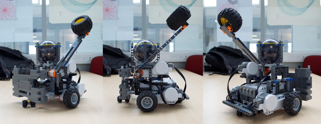
The final part of the construction was the placement of the IR-Emitter, which should emit 360 degrees both horizontally and vertically. For this purpose we used the IR ball for the Lego football game as it has this exact property. Mounting the IR ball was straightforward, however the mount the for the ball is close to the hitting arm and the arm does graze the mount sometimes. We will keep an eye out for whether this causes any problems but after a few test runs it does not seem to do that. Pictured below is the finished remote controlled robot.

Remote Controlled Robot

Pictures of the remote controlled robot from different angles.

The only thing left was add the limitation on how far the hitting arm should be able to move into the code. First we added a case to the RCanimal-class’ switch for input from the Bluetooth connection:

1
2
3
4
case 9:
	attack = true;
	break;
}

We implemented a thread that listens for the attack command which plays a punch sound, moves the hitting arm down, waits for a bit and then moves the hitting arm back to its upright position.

1
2
3
4
5
6
7
8
9
10
11
12
13
14
15
16
17
18
19
20
21
22
class AttackHandling extends Thread {
	private NXTRegulatedMotor hammer = new NXTRegulatedMotor(MotorPort.A);
 
	public AttackHandling() {
		hammer.setSpeed(hammer.getMaxSpeed());
	}
 
	public void run() {
		while (true) {
			if (attack) {
				Sound.playSample(new File("punch3.wav"));
				hammer.rotateTo(100);
				try {
					Thread.sleep(500);
				} catch (InterruptedException e) { e.printStackTrace(); }
				hammer.rotateTo(0);
				attack = false;
			}
			LCD.drawString("atk: " + attack, 0, 6);
		}
	}
}

Complete System
The state of the system at the moment is the following: First off we have constructed and programmed our autonomous robots to move around in the environment, if it’s hungry and it sees “food” it’ll eat it. If the infrared sensor on the autonomous robot sees the infrared ball placed on the robot controlled by the player it’ll turn and move away from it – in essence try to run away from the player. Furthermore if the ultra sonic sensor detects something within a certain distance it’ll turn and move in a different direction to avoid obstacles, which might be another autonomous robot and thus avoid them bumping into each other. The color sensor used to detect “food” is also used when the robot comes near the edge of the environment where there is a color change in the environment from light gray, read by the sensor as white, to dark gray, read by the sensor as black. In that case the robot turns randomly a number of degrees and checks if it’s out of the dark gray area if so it will continue moving forward. Finally for the autonomous robot it will, when hit on top, detected by the touch sensor, stop moving and start playing a sound as well as moving around itself for about eight seconds.

The remote controlled robot does not have any input from any sensor that it can act upon, it can only wait for input from the user via a Bluetooth connection which is established when the system is set up. As is mentioned in a previous blog entry we had some trouble with the keyboard input as we aren’t using a mechanical keyboard and thus not all key-press combinations can be registered by the non-mechanical keyboard. The user input is recorded on a computer which is also responsible for transmitting it via the Bluetooth connection to the robot. The keys used to control robot is W, A, S, D and the spacebar. Furthermore we have mounted a smartphone on the robot to transmit a video feed to the user which is the player’s point of view. We use Skype video call to transmit video as we have found this to be the best solution for the moment being, as explained in End-course project 2[2].

Finally we’ve made a small video for the system in action which can be seen below or at http://youtu.be/0lu5gPSlYVQ

In the video you see the system as a whole, where all the different parts comes together, how the autonomous robots act according to their motivation and the remote controlled robot influences the game. For instance when the remote controlled robot hits one of the autonomous robots on top it will stop and start spinning around itself, or if the IR sensor detect the IR ball the autonomous robots become scared, turn away and “run” from the remote controlled robot. The video also shows the interaction that the player has with the remote controlled robot, and how “up close and personal” he/she has to be in order to hit an autonomous robot.

Lego Digital Designer
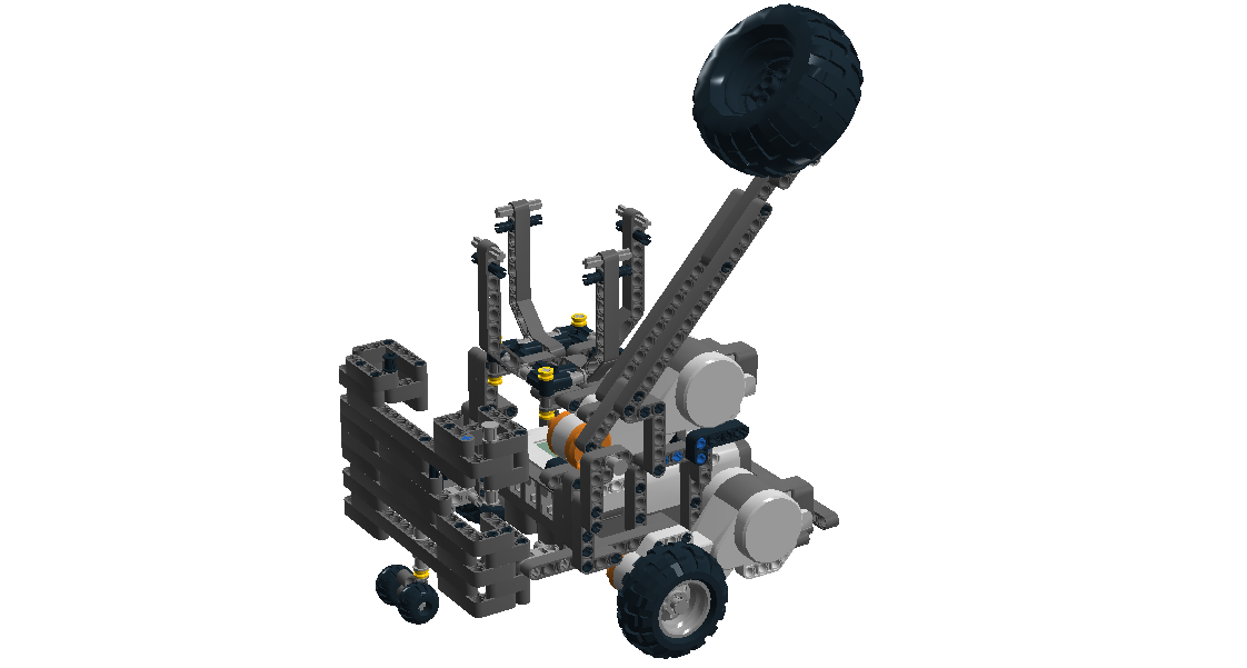
We have constructed a model of the remote controlled robot in Lego Digital Designer, available at http://code.bech.in/digital_control/lab16/RCanimal.lxf.

The remote controlled robot constructed in Lego Digital Designer

The remote controlled robot constructed in Lego Digital Designer

Final Code

References
[1] End-course project 1, http://bech.in/?p=427
[2] End-course project 2, http://bech.in/?p=463
[3] Sørensen, Holm and Altheide, Whack-A-Robot – A Behavior Based Game, http://lego.wikidot.com/report:end-course-project-report

End-course project 4

Date: 6th through 9th of June 2013
Participating group members: Kenneth Baagøe, Morten D. Bech and Thomas Winding
Activity duration: 24 hours

Goal
Complete the development of the behaviors of the autonomous robots.

Plan
Implement the behaviors and test them one by one, then test them when they’re all running together. We might also try to add sounds to the different behaviors.

Progress
As described in an earlier entry [1] we needed five behaviors:

  • Normal
  • Hit by player robot
  • Hunger
  • Scared of player robot
  • Avoid edges/other robots

We had already added some behaviors and started implementing their action() methods, which represent the actual functionality of the behaviors. Among them was the normal, hit and avoid behaviors, where the normal behavior and avoid behaviors seemed to work well.

The hit behavior
As we described in the previous entry [2], we had not decided how to implement the behavior of the autonomous robot when it was hit by the player robot. We had, however already implemented a relatively simple behavior where it would spin in place when hit. After some consideration we decided that we would stick with this behavior. The only thing that was changed in the behavior was that the time it would spin in place was extended as it, in its original incarnation, only spun for three seconds which seemed too short. In the end it ended up being “knocked out” for a total of eight seconds.

The action() method for the hit behavior

1
2
3
4
5
6
7
8
9
10
11
12
public void action() {
	suppressed = false;
	active = true;
	Sound.playSample(new File("PacManDies.wav"), 100);
	AutAnimal.fastRotation();
	AutAnimal.pilot.rotateRight();
	long startTime = System.currentTimeMillis();
	while (!suppressed && startTime + 8000 > System.currentTimeMillis()) Thread.yield();
	AutAnimal.slowRotation();
	AutAnimal.pilot.stop();
	active = false;
}

The scared behavior
We described a scared behavior in a previous entry [1]. The idea stayed much the same as we imagined then.

This behavior was to rely on the infra-red sensor that we mounted on the front of the autonomous robot, as we planned on using an IR ball on the player robot so the autonomous robots could differentiate between it and other autonomous robots. The autonomous robot would then, when it detects the player robot, try to run away as fast it can.

Using the IR sensor was quite reliable as the values it returned were very consistent. After further looking into the functionality of the sensor we were confused by the fact that the sensor could return five different values with getSensorValue(1), getSensorValue(2) ... getSensorValue(5), where we in the first test simply used the one that returned a value that seemed appropriate. After some experimenting we figured out that the sensor has multiple internal IR receivers, most likely placed in an inverted U-shape. This gave us the opportunity to decide how wide of a viewing angle the autonomous robots could have and after additional experimenting we decided to use receivers two, three and four, giving it a relatively wide viewing angle. Using all five receivers made it able to have an extremely wide viewing angle and be able to detect an infra-red source almost directly behind it, which we felt would make it hard to get close to it with the player robot.

We imagine the sensor has viewing angles that resemble what is shown in the figure below.
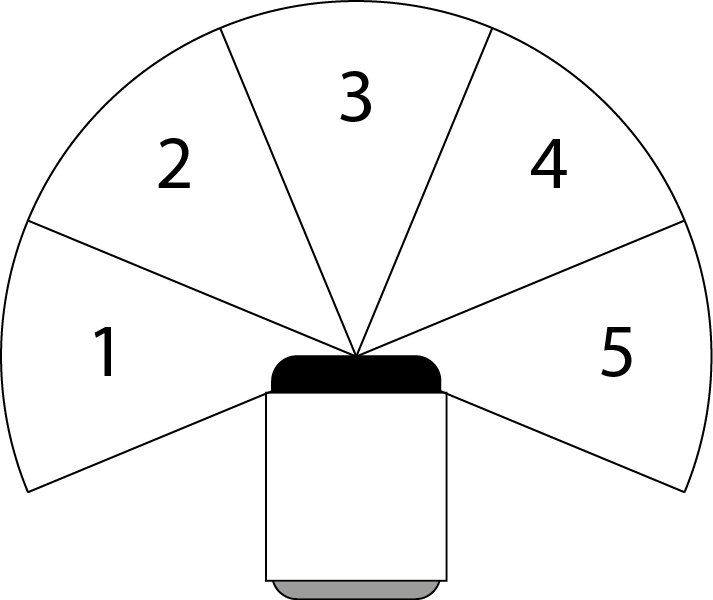
How we imagine the approximate viewing angles of the IR sensor are

How we imagine the approximate viewing angles of the IR sensor are

Thus our takeControl() method for the scared behavior ended up the following:

1
2
3
4
public int takeControl() {
	if (ir.getSensorValue(2) > irThreshold || ir.getSensorValue(3) > irThreshold || ir.getSensorValue(4) > irThreshold) return 200;
	return 0;
}

The behavior we decided the robot would execute when detecting the player robot was to back off and turn away as fast as it could. It was implemented as shown below.

1
2
3
4
5
6
7
8
9
10
11
12
13
public void action() {
    suppressed = false;
    AutAnimal.fastRotation();
    AutAnimal.fastTravel();
    int turn = Math.random() > 0.5 ? -1 : 1;
    int angle = 100 + random.nextInt(60);
    AutAnimal.pilot.travel(-(20+random.nextInt(30)), true);
    while (!suppressed && AutAnimal.pilot.isMoving()) Thread.yield();
    AutAnimal.pilot.rotate(-turn * angle, true);
    while (!suppressed && AutAnimal.pilot.isMoving()) Thread.yield();
    AutAnimal.slowRotation();
    AutAnimal.slowTravel();
}

Running this behavior by itself, it worked as we intended.

The hunger behavior
This behavior was intended to simulate a level of hunger in the autonomous robots. It would start off with the robot not feeling hunger and then slowly increase over time, at some point overtaking the normal, or idle, behavior of the robot. When this happened, the robot would start looking for food and, upon finding some food, it would eat and become satiated.

We implemented this behavior by adding an internal state on the robot keeping track of the hunger and returning this value as its motivation value up to a max of 100.

The implementation of the hunger state

1
2
3
4
5
6
7
8
9
10
11
12
13
14
15
16
public Hunger() {
	Thread t = new Thread() {
		public void run() {
			while (true) {
				hunger++;
				try {
					Thread.sleep(random.nextInt(1000)+3000);
				} catch (InterruptedException e) {
					e.printStackTrace();
				}
			}
		}
	};
	t.setDaemon(true);
	t.start();
}

The takeControl() method of the hunger behavior

1
2
3
4
public int takeControl() {
	if (hunger > 100) {return 100;}
	return hunger;
}

As can be seen in the thread maintaining the hunger state, the hunger increases every 3-4 seconds, we chose to increase it randomly just to add more randomness to the behavior of the robot. When the robots hunger reaches a threshold, namely when its value becomes greater than that of the normal/idle behavior, it starts moving forward at a medium pace. If the robot encounters some food it will grab it, turn a bit and move away with it. At the same time it “eats” the food, resetting the hunger to 0. The robot detects food with the color sensor mounted on the front of it.

We described an idea of the food in entry 3 [2] and the basic idea stayed the same. We did, however, choose to make the food circular instead as we tried with the square and it turned out that the robot was not always able to grab the food. This happened if it came upon the food in some specific angles.

The "food" for the autonomous robots

The “food” for the autonomous robots

Testing
After completing the different behaviors and they seemed to work well in isolated tests, we wanted to try running the robots with all behaviors running. The different behaviors should be decided upon by the arbitrator according to the returned motivation values. Inspired by the diagram by Thiemo Krink [4] we made a similar diagram depicting the motivation network in our autonomous robots, see below.
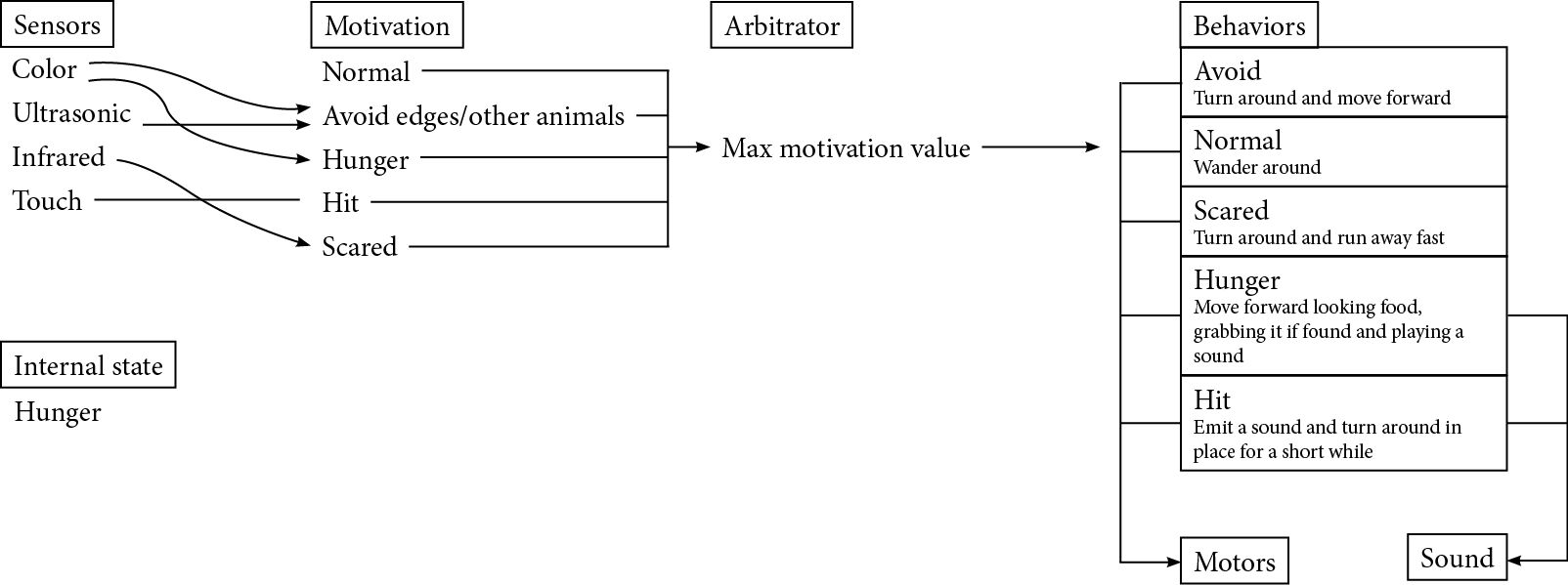
Motivation network for our autonomous robots

Motivation network for our autonomous robots

Running the autonomous robots we quickly noted that the robots would often get stuck on the edges of the arena and that when the robot was hungry and got to the edge of the arena it would alternate between the hungry behavior and avoid behavior rapidly, meaning that it never completed either behavior.

The solution to the robots getting stuck on the edges of the arena was changing the avoid and scared behaviors. The way these behaviors worked was that they had the robot back off when it saw an obstacle/the player robot and turning. We changed these behaviors to, instead of backing up and turning, they would turn and move forward. This made the functionality of the robots much more reliable because the initial functionality of the behaviors had the robots “running blind” when executing these behaviors as they could not rely on the sensors, which were all front-mounted. Changing the behaviors to have the robot moving forwards instead of backwards enabled the robot to, once again, rely on its sensors so it did not bump into obstacles and get stuck on edges. Essentially we established that the robots should never move backwards as it would basically have no idea what it was doing.

To have the robot not rapidly switch between some behaviors that could interrupt each other we implemented an additional motivation value in some of the behaviors that would be returned when the behavior was already active.
Thus we ended up with the following motivation values:

Behavior Motivation value
Normal 10
Scared 0, 200 (IR sensor), 105 (active)
Hit 0, 300 (touch sensor), 205 (active)
Avoid 0, 125 (ultrasonic/color sensor), 205 (active)
Hunger 0-100

After implementing this functionality the problems with “competing” behaviors was solved.

Problems with the color sensor
After running the autonomous robots successfully multiple times we noticed that the robots were suddenly unable to differentiate between the light area and dark area of the arena which we used to tell when the robots were at the edge. After some experimenting we figured out that the cause of the inconsistencies in the color sensor was caused by a change in lighting in the room, it seemed that it got too light in the room when it was cloudy for the color sensor to be able to tell the light area from the dark. This meant that the robot would simply rotate in place since that was the initial part of the avoid behavior.

To solve this problem we mounted shielding around the color sensor which made the readings of the sensor reliable once again.
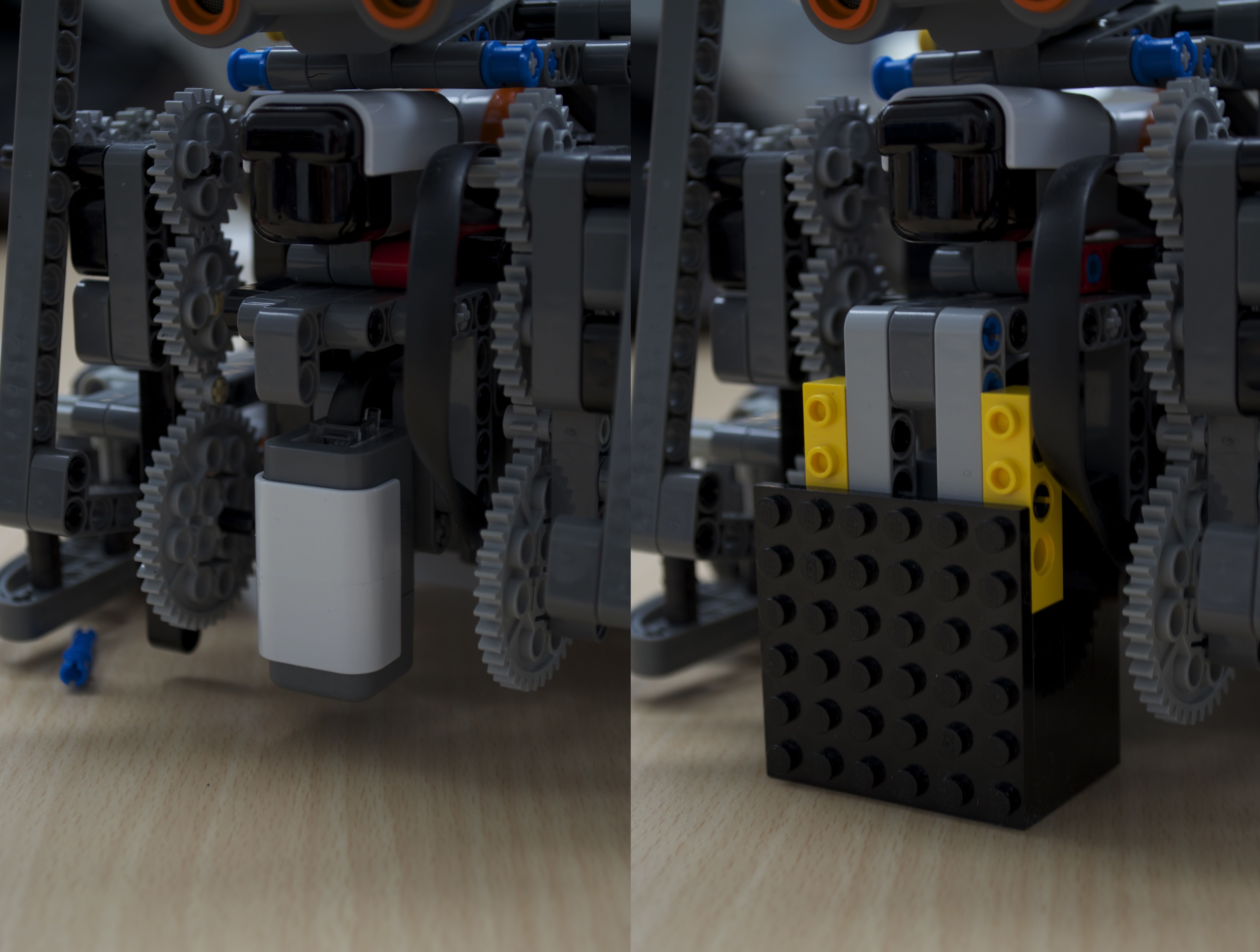
The color sensor before and after adding light shielding

The color sensor before and after adding light shielding

This, however, presented a new problem: The shielding on the sensor had to be very close to the ground in order to function properly. This meant that the sensor was now not able to hover above the red Lego plates that protruded from the “food”, the shielding would hit it. Thus the robot would simply push the food in front of it and never detect it when hungry.

The problem we encountered with the "food" after mounting light-shielding to the colorsensor

The problem we encountered with the “food” after mounting light-shielding to the colorsensor

To solve this new problem we exchanged the protruding Lego disk from the food to one made of cardboard which was thin enough that sensor could once again go over it and detect it.

The "food" for the robots with the Lego base exchanged for one made of cardboard

The “food” for the robots with the Lego base exchanged for one made of cardboard

Adding sound
We wanted to try adding some sound to the game to make it more entertaining. Playing sound on the NXT is very simple when using wave files as you simply use the Sound.playSample("file") method. The largest problem in this regard is the very limited Flash memory of 256KB, where the lejOS firmware seems to take up about 100KB. We tried adding two different small wave files that we found and noted that the NXT brick was only able to play one of them. The cause of this was that the NXT was only able to play 8-bit samples and one of them was, most likely, a 16-bit sample. Also worth mentioning is that the speaker on the NXT does not seem to be of a very good quality and thus good quality sound samples are probably wasted on it. We used this to our advantage, using the program Switch Sound File Converter[3], to reduce the quality, and also size, of sound samples and at the same time converting them to 8-bit samples. This gave us the chance to have multiple sound samples on each robot as the sound samples were usually in the 50-100KB range even if they were less than a second long since drastically reducing the sample rate did the same to the file size, often reducing the file to 5-10KB.

As the NXT seems to play sounds in a separate thread we also did not have to worry about it blocking the program on the robot and thus we could simply add in a sound where we wanted it without needing any major changes in the program. So far we added an eating sound when the robot finds food and a sound when the robot is hit.

Backlog
The autonomous robots are now working as we intended. We might try to find some more sounds to play on the robots when they are executing different behaviors but this will probably not be prioritized. We still need to finish construction on the remote controlled player robot which we will work on next time. The program for the remote controlled robot is mostly working, but we still need to experiment with its “weapon” and figure out how much the motor will need to rotate and whether it can properly “knock out” the autonomous robots. Additionally we might try to find some sound samples to play on the remote controlled robot.

Lego Digital Designer
We have constructed a model of the autonomous robot in Lego Digital Designer, available at http://code.bech.in/digital_control/lab15/AutAnimal.lxf.
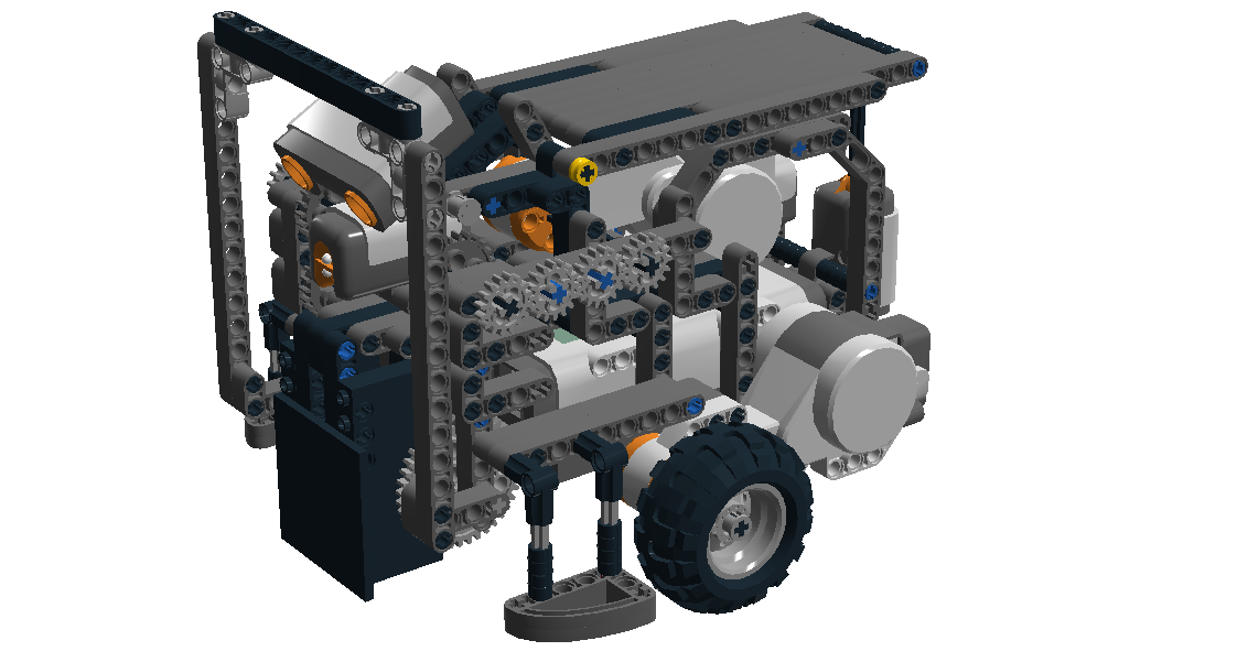
The autonomous robot constructed in Lego Digital Designer

The autonomous robot constructed in Lego Digital Designer

References
[1] End-course project 2, http://bech.in/?p=463
[2] End-course project 3, http://bech.in/?p=472
[3] http://www.nch.com.au/switch/index.html
[4] Thiemo Krink (in prep.), Motivation Networks – A Biological Model for Autonomous Agent Control

End-course project 3

Date: 25th of May 2013
Participating group members: Morten D. Bech and Thomas Winding
Activity duration: 5.5 hours

Goal
To further develop the behaviors of the autonomous robots and build one or more of them.

Plan
Modify the idle behavior of the robot so that it drives around randomly. Add the remaining behaviors and try to make them behave as we imagined they would.

Progress
We implemented the normal, or “idle”, behavior to have the robot move slowly around in a random manner. Its takeControl() method always returns a motivation value of 20 and should generally be the lowest value returned as this is the behavior we want it to have when nothing else is happening with the robot. The action() method of the robot can be seen below.

1
2
3
4
5
6
7
8
9
10
11
12
13
14
15
16
17
18
19
public void action() {
	suppressed = false;
 
	int action = random.nextInt(2)+1;
	if (action == 1) {
		int direction = Math.random() > 0.5 ? -1 : 1;
		AutAnimal.pilot.travel(direction*(random.nextInt(20)+5), true);
	}
	if (action == 2) {
		int turn = Math.random() > 0.5 ? -1 : 1;
		int angle = 10 + random.nextInt(40);
		AutAnimal.pilot.rotate(turn * angle, true);
	}
 
	while (!suppressed && AutAnimal.pilot.isMoving()) {
		Thread.yield();
	}
	AutAnimal.pilot.stop();
}

Subsequently we added the remaining behavior classes and started implementing their functionality. The behavior that avoids other autonomous robots and the edges of the arena was fairly straightforward as the functionality was much akin to avoiding the player robot however it did not need to move as quickly since it is not “scared” of the other robots.

As we have not decided quite yet what should actually happen when the robot is hit by the player robot, it has been set to spin in place for three seconds when it is hit.

The hunger behavior of the robot is still not quite finalized as well. So far we imagine the hunger behavior will function as follows: The hunger of the robot increases over time, when the robot reaches some level of hunger it will start moving at a medium speed and move forward, still avoiding obstacles and the player robot. When it finds some food it will grab it with its “arms” and try to run away with it.

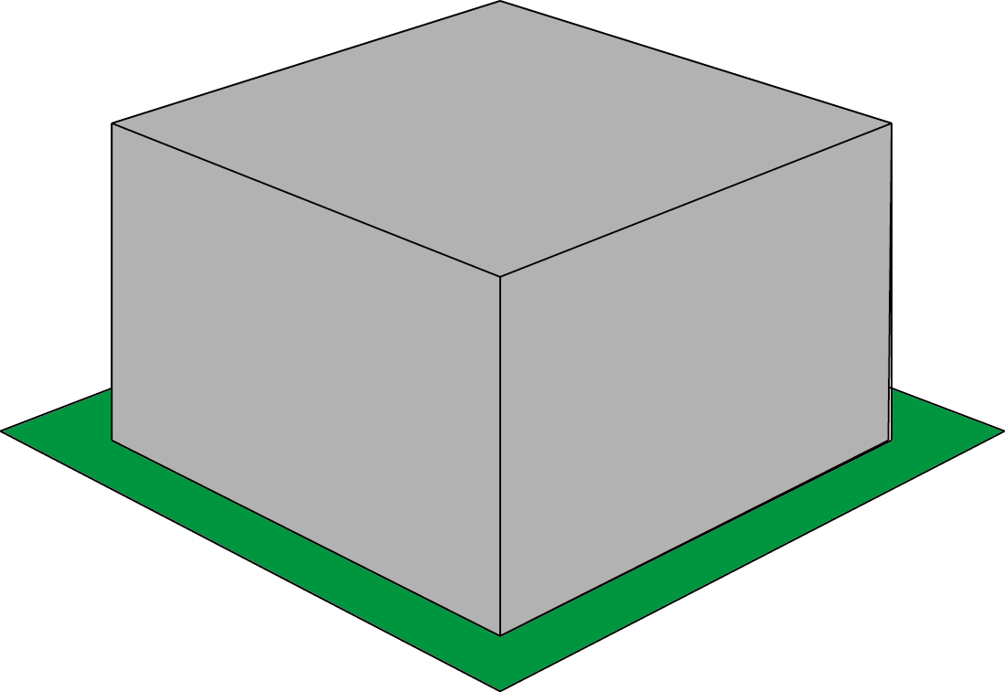
The way the robot will identify food is with a color sensor mounted on front of the robot and pointing downwards, the “food” will be a block of some sort with a green base that extends out from the block itself, enabling the robot to see it.

The extended base of the food enables the robot to detect it with the color sensor

The extended base of the food enables the robot to detect it with the color sensor

"Artists" rendition of the food block

“Artists” rendition of the food block

Building of the autonomous robot
The robot needs to have three sensors in front, namely the IR Sensor, Ultra Sonic Sensor and Color Sensor. Furthermore it should have a grabbing arm for grabbing the food as described above. The robot also needs some kind of pressure plate on top to detect when it’s been hit by the player. To make hitting this plate easier we will try to keep the profile of the robot as low as possible.

In the robots first incarnation the Ultra Sonic and IR Sensors were placed in front of the Color Sensor, but this gave us a problem with the grabbing arm which would have to be very long if we wanted to move it into a upright position. Therefore this design was abandoned and the two sensors were placed on top of the Color Sensor instead. The Ultra Sonic Sensor was placed as the topmost sensor and we angled it slightly downwards so it could detect the edge of the arena. Right behind the Ultra Sonic Sensor the pressure plate is placed which is connected to a Touch Sensor.

Due to our construction of the robot it is relatively hard to get to push the buttons on the NXT and connecting the cables to the sensors and NXT is going to be a tight fit as well, we have not mounted them yet. A solution to not being able to press the buttons could be to have the program on the NXT autorun when it is turned on and then use the pressure plate on top of the robot as a start button. Pictured below is our construction of the robot.

Autonomous Robot

Pictures of the autonomous robot for the game, completed with all the necessary sensor and motors.

End-course project 2

Date: 23rd of May 2013
Participating group members: Kenneth Baagøe, Morten D. Bech and Thomas Winding
Activity duration: 7 hours

Goal
Further refining the player robot described in previous entry[9] and possibly start constructing the autonomous robots for the game.

Plan
Identify the bug that we noticed last time that caused problems with attacking and fix it. Add the video feed from the player robot directly into the Java controller application that runs on the PC. Possibly start developing the program for the autonomous robots and building them.

Progress
Controlling the robot
The problem with the robot being unable to attack when steering left while moving forward or steering right while moving backwards stumped us last time. The solution, however, was not very complicated and can be explained by with the term key blocking/ghosting[1][2]. Key blocking basically means that a keyboard can only handle three keypresses at a time and while that was what we were trying to do, it is only certain combinations it could handle, which we inadvertently demonstrated: When pressing e.g. the left arrow and the up arrow the channel that the space bar was trying to send on was blocked. Finally we solved the problem by moving the controls from the arrow keys to the WASD keys which did not cause blocking in the keyboard.

Video feed in the Java application
We tried to add the video feed from an Android smartphone directly into the Java controller application that runs on the PC. We were able to get a feed running using the media functionality of JavaFX and we tried using the VLCj library[3] that utilize the streaming functionality of the VLC media player[4]. On the smartphone we used the applications IP webcam[5] and spydroid[6].

As mentioned we were able to get a feed running using the JavaFX library, this was done in combination with IP webcam application for the smartphone, see code below. We had to set up a LAN as the application was only able to stream on a local network. The problem we encountered with this solution was that there was a very noticable delay on the feed, 3-4 seconds. Unfortunately we were not able to figure out a way to circumvent this delay and thus the solution was not usable as a delay that long made it too hard to control the robot properly.

Video feed in Java:

1
2
3
4
5
6
7
8
9
10
11
12
13
14
15
16
17
18
19
20
21
22
23
24
25
26
27
28
29
30
import javafx.application.Application;
import javafx.scene.Group;
import javafx.scene.Scene;
import javafx.scene.media.Media;
import javafx.scene.media.MediaView;
import javafx.stage.Stage;
 
public class MediaPlayer extends Application {
private static final String MEDIA_URL = "http://192.168.10.101:8080";
 
public void start(Stage primaryStage) throws Exception {
	primaryStage.setTitle("JavaFX Media Player");
	Group root = new Group();
	Scene scene = new Scene(root, 640, 480);
 
	Media media = new Media(MEDIA_URL);
	javafx.scene.media.MediaPlayer mediaPlayer = new javafx.scene.media.MediaPlayer(media);
	mediaPlayer.setAutoPlay(true);
 
	MediaView mediaView = new MediaView(mediaPlayer);
	((Group)scene.getRoot()).getChildren().add(mediaView);
 
	primaryStage.setScene(scene);
	primaryStage.show();
}
 
public static void main(String[] args) {
	launch(args);
}
}

We also tried using the spydroid application in conjunction with the VLCj library but were unable to get the video feed running in Java, it would connect but there would be no picture. When we opened the stream in a browser instead, we saw that this application had a delay comparable to the one described above. Thus we chose to not pursue the use of this application any more.

Autonomous robots
We started developing the program for the autonomous robots and decided that they should be motivation based[8]. We had a good idea of how the robots should function and thus we needed to translate that into different behaviors for the robots. The behaviors included:
– When the robot was “idle”
– When the robot was hungry
– When the robot had been hit by the player robot
– When the robot saw the player robot
– When the robot saw an obstacle / other autonomous robot

As we had done motivation based robots before[7] we were able to draw inspiration from the program we developed then and reused the arbitrator and behavior interface.

We added a simple idle behavior that rotated the robot in place and added the behavior that made robot scared when it saw the player robot so we could test the IR receiver which we wanted to use to detect the player robot. The takeControl() would then return a high value when the robot is relatively close to the player robot and otherwise return zero.

1
2
3
4
public int takeControl() {
	if (ir.getSensorValue(3) > 160) return 200;
	return 0;
}

As the robot moves slowly during its idle behavior we wanted it to look like it got scared when it saw the player robot and thus made it back off a random distance fast when it sees the player followed by turning either left or right which can be seen in the code below.

1
2
3
4
5
6
7
8
9
10
11
12
13
public void action() {
	suppressed = false;
	AutAnimal.fastRotation();
	AutAnimal.fastTravel();
	int turn = Math.random() > 0.5 ? -1 : 1;
	int angle = 100 + random.nextInt(60);
	AutAnimal.pilot.travel(-(20+random.nextInt(30)), true);
	while (!suppressed && AutAnimal.pilot.isMoving()) Thread.yield();
	AutAnimal.pilot.rotate(-turn * angle, true);
	while (!suppressed && AutAnimal.pilot.isMoving()) Thread.yield();
	AutAnimal.slowRotation();
	AutAnimal.slowTravel();
}

Backlog
As was mentioned we were unfortunately not able to reach a usable solution to adding the camera feed into the controller application and decided not to spend any more time on trying to solve it for the time being. We would like to return to this problem at a later stage if we have the time to do so.

We have started implementing the behaviors and will continue working on them next time.

Finally, if we decide that we really want to use the arrow keys on the keyboard to control robot we might need to get a hold on a mechanical keyboard.

References
[1] http://www.braille2000.com/brl2000/KeyboardReq.htm
[2] http://en.wikipedia.org/wiki/Rollover_%28key%29
[3] http://code.google.com/p/vlcj/
[4] http://www.videolan.org/vlc/
[5] http://ip-webcam.appspot.com/
[6] http://code.google.com/p/spydroid-ipcamera/
[7] Lesson 10, http://bech.in/?p=362
[8] Thiemo Krink (in prep.), Motivation Networks – A Biological Model for Autonomous Agent Control
[9] End-course project 1, http://bech.in/?p=427

End-course project 1

Date: 16th of May 2013
Participating group members: Kenneth Baagøe, Morten D. Bech and Thomas Winding
Activity duration: 7 hours

Goal
The goal of this lab session is to discuss our project idea with Ole, and, if he approves of it, start constructing and programming the remote controlled animal plus finding a proper way of streaming video from the robot to a computer or tablet.

Plan
The plan is straightforward once we have received the approval from Ole. We start by establishing a BlueTooth connection between the NXT and a computer which we have done in a previous lab session. Next up we need to encode key presses on computer in such a way that it can be transmitted over a BlueTooth connection and the NXT needs to decode them and act appropriately. Furthermore we need to find a device that can stream video wirelessly.

Progress
After having a quick chat with Ole Caprani we got started on the RC animal as he approved our idea and gave us some project blogs from last year we could use as inspiration for our project. We split our work into two separate jobs, one was to build a phone holder and the other was to program the remote control software for the NXT and computer.

The simple part of building the phone mount was assigned to Morten and he quickly built a first prototype which was rebuilt to accommodate the possibility of putting the phone in and taking it out again without having to take the whole mount apart each time. On the picture below you can see the phone mount mounted to the standard robot we used in the week following up to the project start.

Phone holder

Different views of the phone holder.

The other part we worked with was the software for remote controlling the robot via a BlueTooth connection. As we had worked with a BlueTooth connection to the robot before we could draw some inspiration from that project, this meant that the basic problem of establishing the connection was easily solved:
We wrote a BlueTooth connection class for the NXT that runs in a seperate thread and accepts connections. When the thread receives some data from the controller it relays it to the thread controlling the robot.

The first implementation of the code was able to accept single keypresses on the controller, the controller in this case being a PC, which meant that the robot could simply move forward, backward and turn in place. When we tested this functionality we noted that being able to steer while moving forward would be useful and thus we set about implementing this.
We established an enumerated class to tell which action was supposed to be sent to the robot and a number of booleans to tell which buttons were pressed. When a button is pressed the boolean for it is set to true and vice versa.

1
private enum State {FORWARD, BACKWARD, RIGHT, LEFT, FORWARD_RIGHT, FORWARD_LEFT, BACKWARD_RIGHT, BACKWARD_LEFT, STOP};
1
private boolean upPressed = false, downPressed = false, leftPressed = false, rightPressed = false, spacePressed = false;

Following this the updateState() method is called and finally the action is sent to the robot via the sendMove() method.

1
2
3
4
5
6
7
8
9
10
11
private void updateState() {
	if (upPressed && rightPressed) { state = State.FORWARD_RIGHT; return; }
	if (upPressed && leftPressed) { state = State.FORWARD_LEFT; return; }
	if (downPressed && rightPressed) { state = State.BACKWARD_RIGHT; return; }
	if (downPressed && leftPressed) { state = State.BACKWARD_LEFT; return; }
	if (upPressed) { state = State.FORWARD; return; }
	if (downPressed) { state = State.BACKWARD; return; }
	if (rightPressed) { state = State.RIGHT; return; }
	if (leftPressed) { state = State.LEFT; return; }
	state = State.STOP;
}
1
2
3
4
5
6
7
8
9
10
11
12
13
14
15
16
17
18
19
20
21
22
private void sendMove() {
	int action;
	switch (state) {
		default:
			action = 0;
			break;
		case FORWARD:
			action = 1;
			break;
		//...
		case BACKWARD_LEFT:
			action = 8;
			break;
	}
 
	try {
		dos.writeInt(action);
		dos.flush();
	} catch (Exception e) {
		e.printStackTrace();
	}
}

When the robot receives the action it then acts accordingly via a simple switch:

1
2
3
4
5
6
7
8
9
10
11
12
13
14
15
16
17
switch (action) {
	default:
		pilot.stop();
		break;
	case 1:
		pilot.forward();
		break;
	case 2:
		pilot.backward();
		break;
 
	//...
 
	case 8:
		pilot.steerBackward(-turnSharpness);
		break;
}

When we got the code working we were able to drive around using the remote control software and a Skype video chat to live stream the view of the robot. We had a bit of fun driving the robot around in the Zuse building and we made a small video of the robot which can be viewed below.

The video shows the robot driving on one of the arenas while in the corner of the video you can see the view available for the controller – the two feeds are synchronized.

Backlog
We implemented a quick way of telling the robot to attack, however, when we tested this we noted that when the robot was moving forward and steering left or moving backwards and steering right it was not able to attack. We need to look into what the cause of this bug is.

We would like to have a single Java application in which the video stream is shown and key presses are detected and transmitted to the robot, instead of the current solution using Skype to send the video feed, however we are going leave it be for the moment as there is plenty of other stuff that doesn’t work yet which we also have to complete.

Code
BTconnection.java
RCanimal.java

End-course project 0

Date: 9th of May 2013
Participating group members: Kenneth Baagøe, Morten D. Bech and Thomas Winding
Activity duration: 6 hours

Prelude
For the exam of the course Digital Control we have to make a project based on some of the topics presented during the course.

Goal
The goal of this lab session is to decide on a project we would like to do and describe it in details with regards to hardware, software and possible difficult problems we might able to see now in the project.

Plan
First we will brainstorm some different ideas we can come up with and then select three and describe these in a bit more detail, finally will we select one which we will.

Ideas
Mapping (Inspired by Maja Mataric[1])
Mapping out the layout of a room and navigating it without bumping in to objects that might block the robots path. Might need to be in a fixed environment as a random environment could be too demanding.

RC animal / autonomous animals
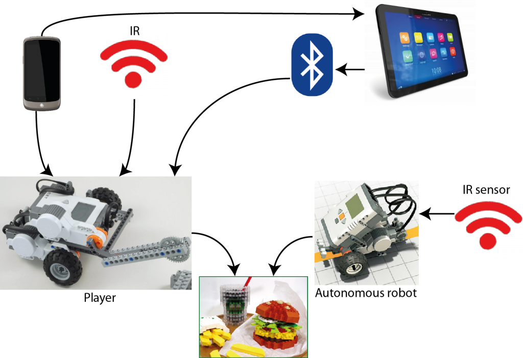
Consists of a single remote controlled “animal” and a number of autonomous “animals”. The autonomous robots try to steal food from the the player (RC animal) while the player incapacitates them to stop them. Additionally the player animal is controlled though a tablet of some sort which also provides a point of view from the animal.

WRO Senior High School Regular Challenge
Work on the challenge and came up with one or a couple of possible designs for a robot that complete the challenge. Also compare software possibilities between NXT-G and LeJOS, because the only software allowed at the international finale is NXT-G. The challenge can be found here.

Flock of robots
A flock of robots that are able to propagate updates to other robots. Basically, if a single robot of the flock receives an update it can then send the update to another robot(s) and they can, in turn, send it to yet another robot.

Zombie robots
Builds on the flock of robots. One robot could get “infected” with a zombie virus and start infecting other robots. The healthy robots try to avoid the zombies.

Evolution/self-learning
A robot that is able to evolve. Could be realized with a line-following PID controller-based robot that would adjust the PID values automatically and compare the run times, thus finding the optimal values for the PID controller. Would probably also need a way to find its way home to the start position in case the PID values throw it off the track.

Soccer/penalty-kick game[2]
A game where the player could control either the robot that would kick the ball and an autonomous robot would act as goalkeeper or vice versa.

Top 3
We have selected following three ideas as our top 3:

  • Mapping
  • RC animal / autonomous animals
  • Zombie robots

An addition that can probably be used in most of our ideas, a holonomic drive allows a robot to drive in all directions without turning, which think could be funny to incorporate. We will present the three ideas in a little more detail and technical perspective.

Mapping
Hardware/physical
For the mapping robot we would need the following hardware:

  • One NXT brick
  • Sensors for detection (Ultrasonic sensor and color/light sensor)
  • Landmarks
  • Environment
  • Movable obstacles

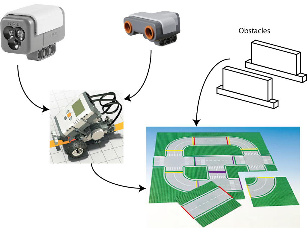
The environment will be a roadlike environment, made up from several squares (see http://legolab.cs.au.dk/DigitalControl.dir/city.jpg for an example), which we can most likely make/print while obstacles can be mostly anything that will block the robot. Landmarks can e.g. be colored lines at the edge of a square so the robot knows when it enters a new square.

Software
On the software side we will use lejOS to program the robot in Java. Controlling the robot will be handled with a Navigator. For an initial run with the robot to discover what the environment looks like we will need some sort of discovery protocol. Furthermore the robot should be able to plan a path that would be the shortest possible when it needs to go somewhere, it should also be able to recalculate a new path if the shortest path is blocked.

Expected difficulties
We believe that the implementation of the planning part of the robot will be somewhat difficult to write.

Expectations
We believe we will be able to fully implement this idea and have the robot working as described in the idea section.

Components need for the Mapping project.

Components need for the Mapping project.

RC animal/autonomous animals
Hardware
1 NXT for the RC robot + an IR emitter.
4 NXT for the animals + IR sensors.
1 laptop/PC/tablet.
1 smartphone.
Environment: We’ll need an arena in which the event will take place. The driver shall not be able to see this though.

Software
We’ll need streaming software for live video stream of the RC-robot(using Skype could be a solution in this particular situation). In able to manage the robot we’ll also have to find/code some protocol(s) that can be used. Motivation based animals.

Expected difficulties
It will be a challenge creating a low-latency live video stream, and we might have to create some sort of overlay using Skype instead of start coding from scratch. Furthermore the latency from the controller(laptop/PC/tablet) to the NXT we will consider as a challenge.

Expectations
We’re expecting the robot to be controlled remotely but not necessarily controlled from a tablet. We also expect the animals to have a behavior based “mind”.

Components need for the RC animal project.

Components need for the RC animal project.

Attack of the Zombies!
As explained earlier the a group of robots “live” in some environment where one of the robots gets infected by an virus and now tries to infect the other robots. We imagine that the environment is some flat surface surround by a wall to keep the robots in a confined space. Therefore the robots must have some way of sensing the wall. As what makes a robot a infected robot and how does it infect other robots? One solution is mount an IR-emitter and an IR-sensor on all the robot, the infected once will turn on their emitter which gives the not infected ones a chance to survive. The placement of the IR-sensor then becomes crucial, is it place as on mammal or predator? Furthermore how does a zombie infect another robot? It could be done is several ways, one it to communicate it through bluetooth every time a robot hits another robot, but this might also conflict with the wall detection.

Hardware
For this project we are going to need approx. 5 robots, a flat surface with an edge around it, same number of IR-emitter and IR-sensors as robots. The IR-emitter could be something we constructed our self which include some LEDs as well to indicate towards the viewer which robot are infected and which aren’t.

Software
The software is going to need two states that it can change between, it might be implemented as a Strategy pattern or as a simply simple state object. Also we need some implementation of change from one state to other and back again for resetting, which could be done via BlueTooth. Also we need to be able to infect the first Zombie. Finally the software of the for the not infect could be motivation based.

Expected difficulties
One of the concerns we have for this project is how we indicate that a robot is infected, both to the other robots and the viewer, if we were to construct our own emitter we could take up a lot of time. Secondly we are concerned about the rate that the infection happens with, we don’t want the rate to be too fast nor too slow, because we don’t want it to be too borrowing nor over too fast.

Expectations
We expect that we would be able to complete the project in its full, but if can the infection rate perfect is another question.

Components need for the Attack of the Zombie project

Components need for the Attack of the Zombie project

And the winner is
We have selected RC aminal as the project we would like to do for our end-course project, however we wouldn’t commit to it 100% until we have had a chance to talk to Ole. Our reason for selecting that one is that we found the most fun to do of the three, while all could be interesting to do. Furthermore we have made a small timetable which can be seen be below.

Timetable
So fare we have come up with the following timetable for the project:

Tuesday, 14th of May Talk to Ole regarding our choice of project
Thursday, 16th of May Correct project depend on feedback we get from Ole, work on a remote controlled robot.
Tuesday, 21st of May Complete the remote control if not already done.
Thursday, 23rd of May Construction of environment and robots.

References
[1] Maja J. Mataric, Integration of Representation Into Goal-Driven Behavior-Based Robots, in IEEE Transactions on Robotics and Automation, 8(3), Jun 1992, 304-312.
[2] World Robot Olympiad Gen II Football, http://wro2013.org/challenges/challenges-football