So let me be the first to acknowl that this year the network course more problems than what is good and much of it properly could have been caught with more preparation. The three main problems where the internet connection, DHCP snooping on the access switches, and the configuration of the SMC switches used as access switches. On that note let me make it clear that the two first problems where solved during the first evening and the last problem wasn’t solved completely only to the best of our ability. The general network worked very well and we didn’t have any problems with our Cisco hardware after friday evening, apart from a single Layer 1 problem – where someone had disconnected the uplink cable to a switch.
The size of network and traffic makes it equivalent to a medium sized company. We have 2200 participants with relative high requirements to bandwidth and not to mention several streamers. This puts so pressure on the distribution and core hardware. A typical construction to obtain highest possible speed is to use what I would call a double star topology. The first star topology is from the core switches/router to the distribution switches and the second star topology is from the distribution switches to the access switches. This is what DreamHack uses with some built-in redundancies. We’ve however chosen a different topology for our network, namely what I would call a loop-star topology. The top topology is a loop where the core and distribution switches/routers are connected in one or more loop(s), and the bottom topology is a star from the distribution switches to the access switches. The top topology does of course places some requirements to the core and distribution in terms of routing protocols, if you choose to use layer 3 between them as we did.
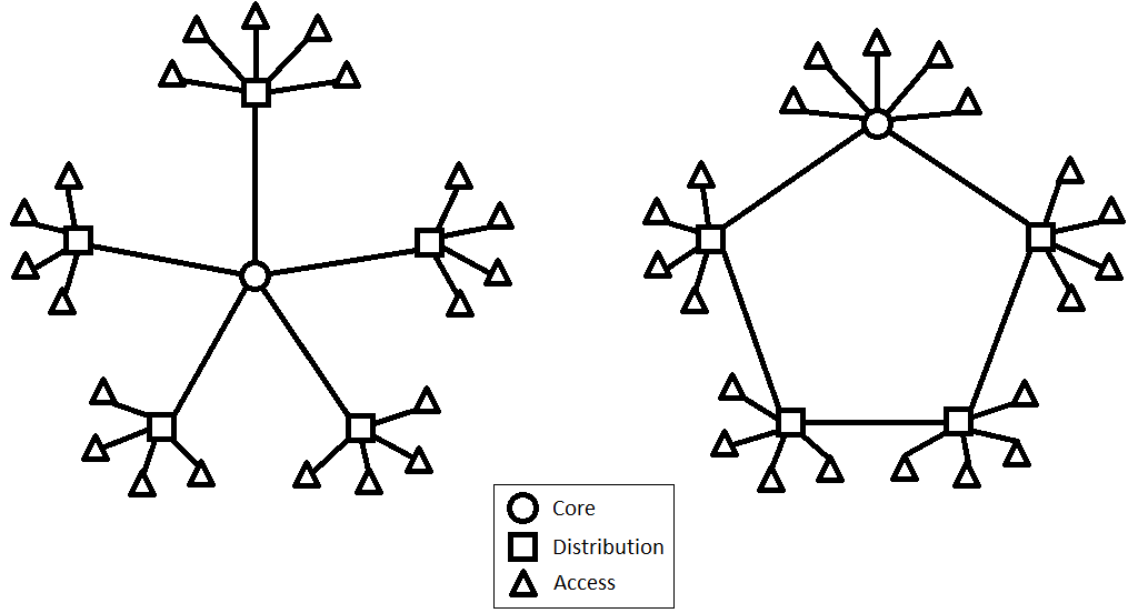
Double star and Loop-star topologies
The protocol we choose for our layer 3 routing was OSPF, as the original design included some HP ProCurve switches for distribution and EIGRP is Cisco proprietary and those not really an option. One of the remaining possibilities was RIP, but this protocol doesn’t propagate fast enough in a loop topology and those isn’t really an option either. The reason for choosing the loop topology is quite simply redundancy in the distribution layer and the idea of doing it this way is taken from the construction of the network made for SL2012 (Spejdernes Lejr 2012 – http://sl2012.dk/en), where I helped out as a network technician. The major differences from SL2012 to NPF#14 is the number of loops and bandwidth between the distribution points – SL2012 had a single one gigabit loop and two places where the internet was connected to the loop, while we at NPF#14 had two loops, one with two gigabits for administrative purposes and one with four gigabit for the participants, and only a single place where four gigabit internet was connected. Our core consisted of two Cisco switches in stack, each of the participants distribution switches was a 48-port Cisco switch and each of the administrative distribution switches was a 24-port Cisco switch. For the internet we had four 1 gigabit lines which each where setup on a pfSense for NATing on to the different scopes of the internet-lines, and we then used the Cisco layer 3 protocol for load-balancing the four lines. Finally everything from the distribution switches to the access switches is layer 2 based, and this also the way we control the number of people on the same subnet and on the same public IP as we don’t have a public IP per participant.
But enough about the construction of our network let us take a look at the traffic amounts over the 47 hours the event lasted. First of the four internet lines moved 23TB of data, of which 20.2TB was download and 2.8TB was upload. The amount of traffic moved through the core on the participant loop was 21.48TB, 12.9TB on one side and 8.58TB on the other side. The administrative loop on the other hand only moved 1.37TB of data through core switch. With a little math we get that the average load on the participant loop respectively is 625Mbps and 415Mbps, while the administrative loop load average is 66.3Mbps. The average load on the internet from the core was 1.114Gbps, with a measured peak of 2.8Gbps. In the picture below the data is placed on the connections between the switches.
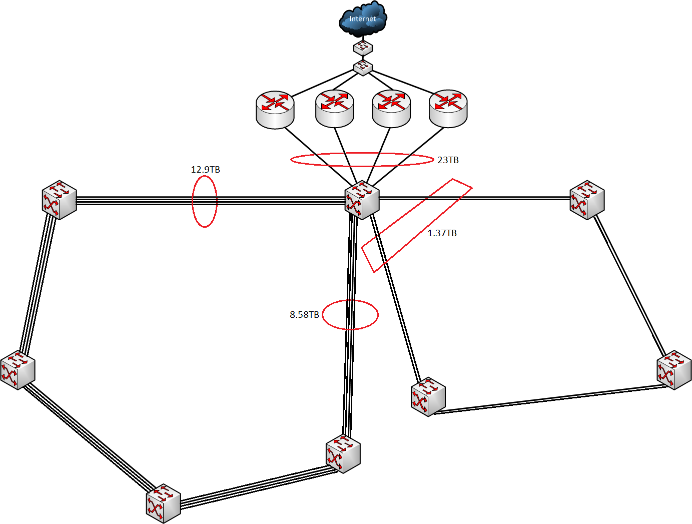
Traffic on different interfaces
We have learned a thing or two from this year’s construction of network, layer 3 routing between distribution points and a multi-loop topology can work for a LAN Party of our size. Furthermore we might be able to reduce the size of the bandwidth on loops a bit, the average loads are fairly low – but this doesn’t say anything about peak load performance which we encounter friday and saturday evening. Therefore for good measure the bandwidth on the different types of loops should properly just stay the same. Depending on the growth next year it might be a reasonable idea to make two participant distribution loops instead of just one and maintain the bandwidth of 4Gbps on both loops. Also depending on growth the bandwidth on the internet has to follow, we’re fairly close to our limit this year.