Lesson 10

Date: 2nd of May 2013
Participating group members: Kenneth Baagøe, Morten D. Bech and Thomas Winding
Activity duration: 5 hours

Goal
The goal of this lesson is to test the BumperCar example provided by lejOS according to the lesson plan. Furthermore the goal is also to expand upon the BumperCar example, also described in the lesson plan.

Plan
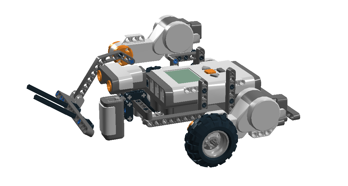
We will use the basic robot from the previous lesson and add an ultrasonic sensor and a touch sensor to it. We will then run the BumperCar example and observe how it functions and describe that. Afterwards we will modify the program according to modifications described in the lesson plan and observe how they work.

Progress
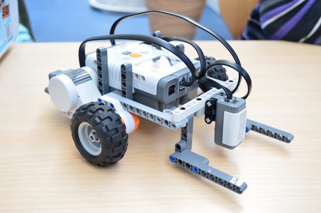
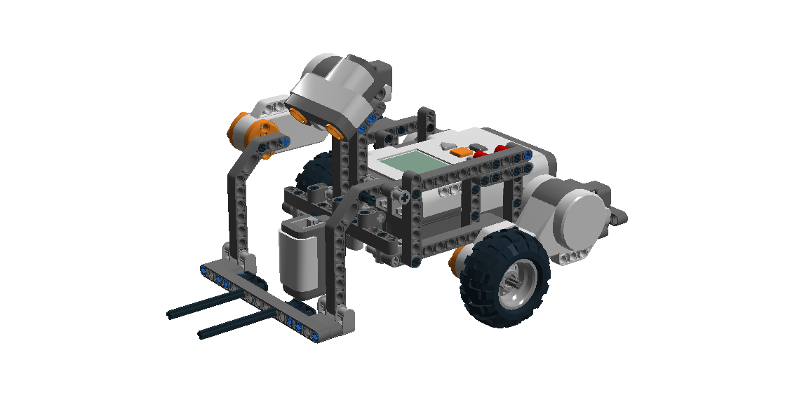
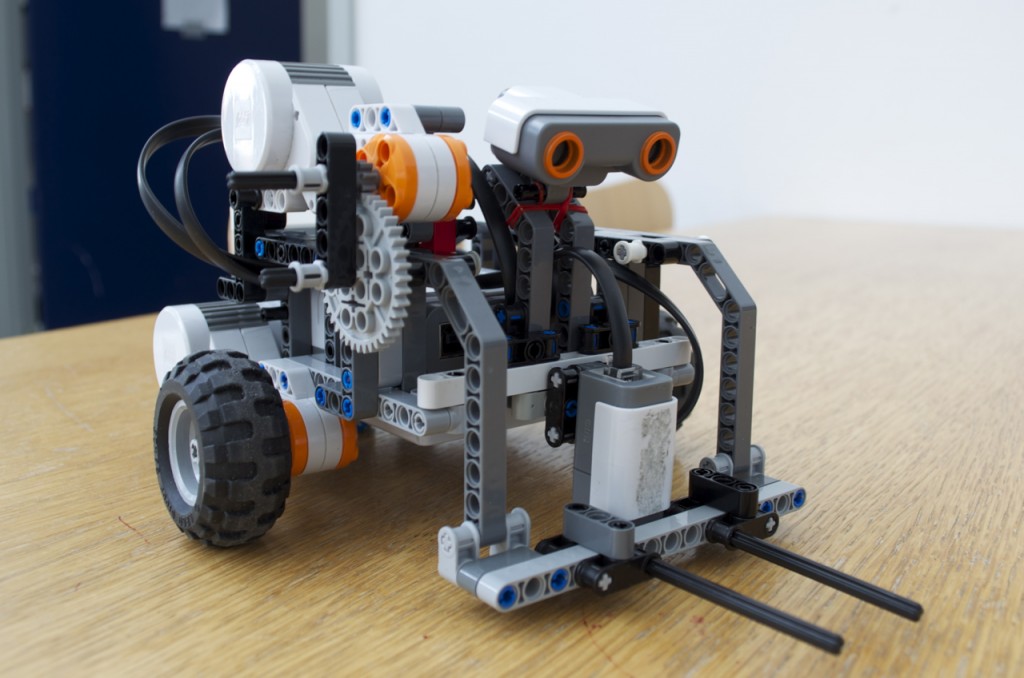
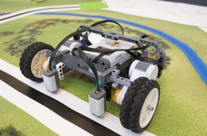
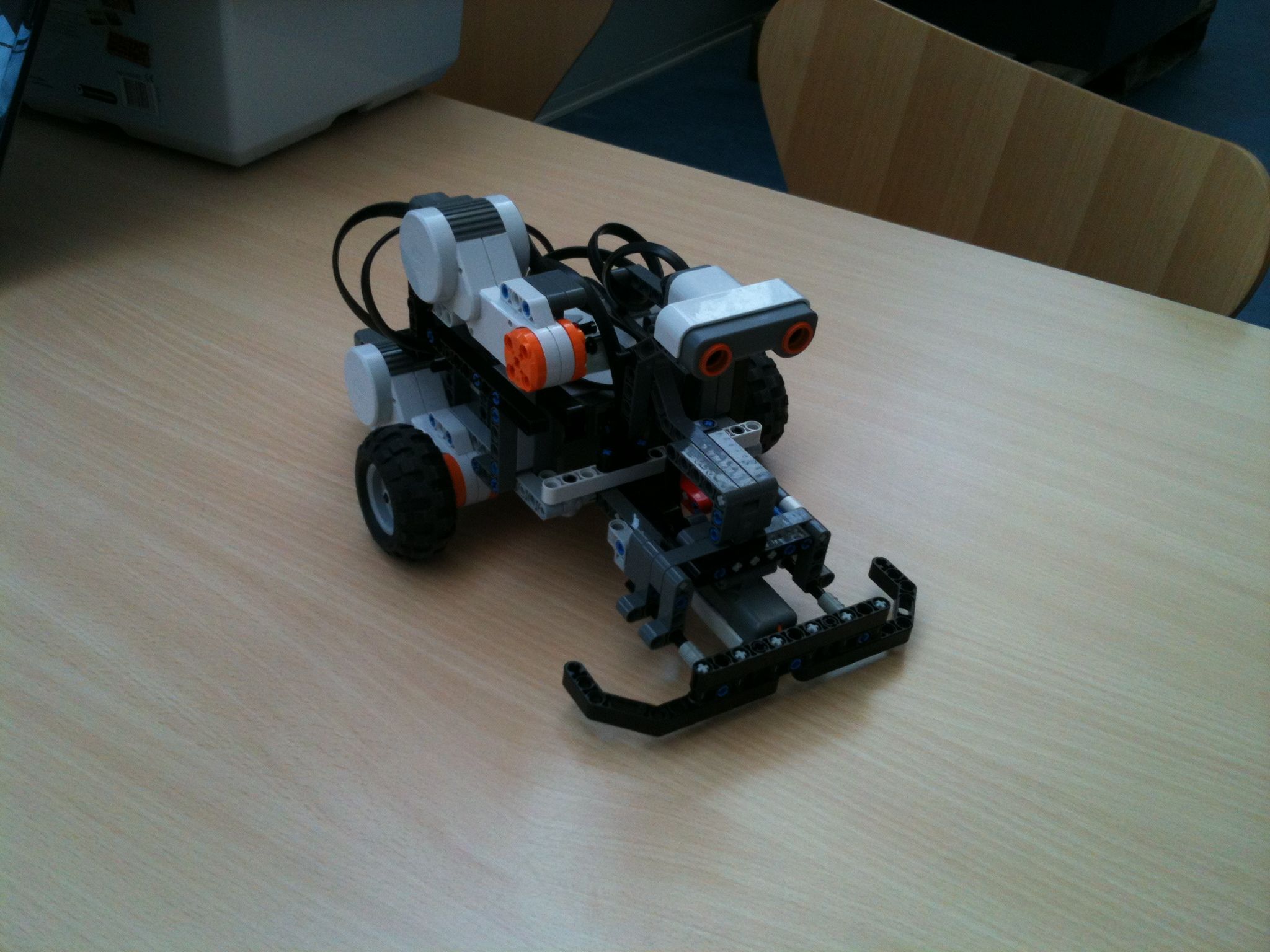
We added the ultrasonic sensor and the touch sensor to the robot and also added a bumper to increase the detection range of the touch sensor (pictured below).

BumperCar

Running the basic BumperCar example we saw that the robot would back off and turn a bit if the ultrasonic sensor was close to an obstacle and the same thing happened if the touch sensor was pressed. We also tried holding down the touch sensor and this resulted in the robot repeatedly backing off and turning slightly. The same behaviour was observed if we held an object close to the ultrasonic sensor. We did, however, have a slight problem with the ultrasonic sensor detecting even a very low obstacle, so to actually test the functionality of the touch sensor we had to temporarily remove the obstacle detection using the ultrasonic sensor.

Adding the Exit behavior
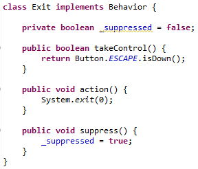
To add the Exit behavior, described in the lesson plan, we added an additional class in the BumperCar class, aptly named Exit, which, like the other classes, implemented the Behavior interface.

The implementation of the class looked like the following:

Implementation of the Exit behavior

Implementation of the Exit behavior

We also had to modify the DetectWall behavior as the suppress method was not implemented properly, it simply did nothing. We went about the basic idea of the suppression the same way that it was done in the DriveForward behavior: We added a _suppressed boolean and implemented the suppress() method to set this boolean to true. Furthermore the action() method of the DetectWall behavior did not properly check for suppression either. Thus we also modified the action() method to immediately return from both of the rotate() methods and added a loop that would yield its timeslices until either the rotation was completed or the behavior was suppressed.

Our modification of the detectWall action

Our modification of the detectWall action

Pressing the escape button seems to exit the program immediately, however from a previous lesson we are aware that the ultrasonic has a short delay of about 30ms when pinging, this will, of course, block the entire program and it is most likely because of the delay being relatively short that we are not able to observe it affecting the program.

Functionality of the Arbitrator class
When the triggering condition of the DetectWall behavior is true, the Arbitrator class does not call the takeControl method of the DriveForward behavior. This can be seen in the code snippet below from the Arbitrator class: It starts from the top priority, checking if the takeControl() method returns true, if it does not, it moves on to the second highest priority and so on. If the triggering condition, however, returns true, the method breaks out of the loop as there is no need to check for the lower priorities.

The loop that determines the highest priority that wants control of the robot

The loop that determines the highest priority that wants control of the robot

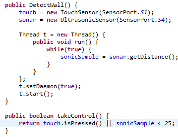
Sampling the ultrasonic sensor in an isolated thread
To alleviate the problem of the ultrasonic sensor delaying the program every time it is sampled, we added the sampling to a thread that would update a variable which the takeControl() method would then evaluate upon.

Implementation of a thread to remove the delay from the sonic sensor

Implementation of a thread to remove the delay from the sonic sensor

Further modifying the DetectWall behavior
To make the robot move backwards for one second before turning we employed the same basic principles as when we modified the DetectWall behavior to be able to be suppressed, as described above. We made the robot move backwards until either a second had passed or the behavior was suppressed by way of another loop, see the code below.

The DetectWall action that moves backwards for one second before turning

The DetectWall action that moves backwards for one second before turning

We were also asked to try to modify the code to make it possible to interrupt the DetectWall action if the touch sensor was pressed or the ultrasonic sensor detected an object. This interruption should then start the action of the behavior again. We were not able to make this part work, we tried adding a boolean to tell if the action was already running and if it was running, the program would stop the motors and start the action over. Unfortunately we couldn’t come up with a solution for this, however when we implemented motivation, which is described in the next section, the interruption worked without any problems. Again we were not exactly sure why.

Motivation
To make the robot motivation based we used the Behavior and Arbitrator implementations provided by Ole Caprani[1][2]. We then changed our modified BumperCar to return integers on the different takeControl() methods instead of booleans. DriveForward was given a low value as it is still a low priority behavior while Exit was given a high value as it should still take precedence over other behaviors. To make DetectWall return a somewhat lower value when it was already active, we added a boolean that was set to true when the action method was run and set to false when the method finished. Thus the takeControl method was able to differentiate between the two states.

takeControl() for the motivation-based DetectWall behavior

takeControl() for the motivation-based DetectWall behavior

Conclusion
We have followed the lesson plan almost to its full extend, the only catch was that we had trouble implementing the DetectWall behaviour so that it could be interrupted while turning if e.g. the touch sensor was activated. However the change to motivation based decision making fixed this problem as we were able to dynamically return higher values if some other action was in progress.

Class-files
BumperCar – Arbitrator
BumperCar – Motivation based
Behavior – Motivation based
Arbitrator – Motivation based

Reference
[1] http://legolab.cs.au.dk/DigitalControl.dir/NXT/Lesson10.dir/Behavior.java
[2] http://legolab.cs.au.dk/DigitalControl.dir/NXT/Lesson10.dir/Arbitrator.java
Lesson 9

Date: 27th of April 2013
Participating group members: Kenneth Baagøe, Morten D. Bech and Thomas Winding
Activity duration: X hours

Goal
The goal of this lab session is to work with the tacho-counter and differentialdrive-pilot as described in the lesson plan.

Plan
Our plan is to follow the instruction and complete the task of the lesson plan.

Progress
Navigation/Blightbot
We started out by doing the test program, Blightbot, by Brian Bagnall [1]. However, as the TachoNavigator class has been removed from lejOS since, we used the Navigator class instead and provided it with an instantiation of the DifferentialPilot class as the move-controller. Controlling the Navigator class basically works in the same way as the TachoNavigator with one small exception: All methods in the Navigator class are non-blocking which means that it’s important to remember to use the waitForStop() method (or alternatively an empty while (isMoving) loop) otherwise the program will simply exit immediately.

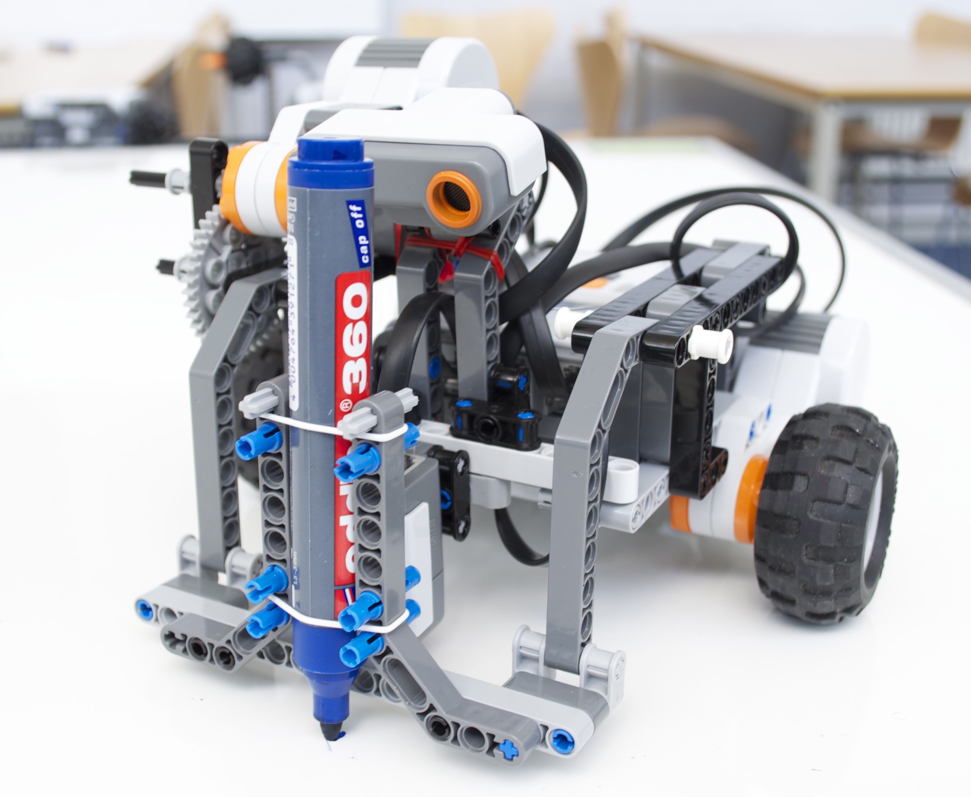
The robot with a whiteboard marker strapped on

The robot with a whiteboard marker strapped on

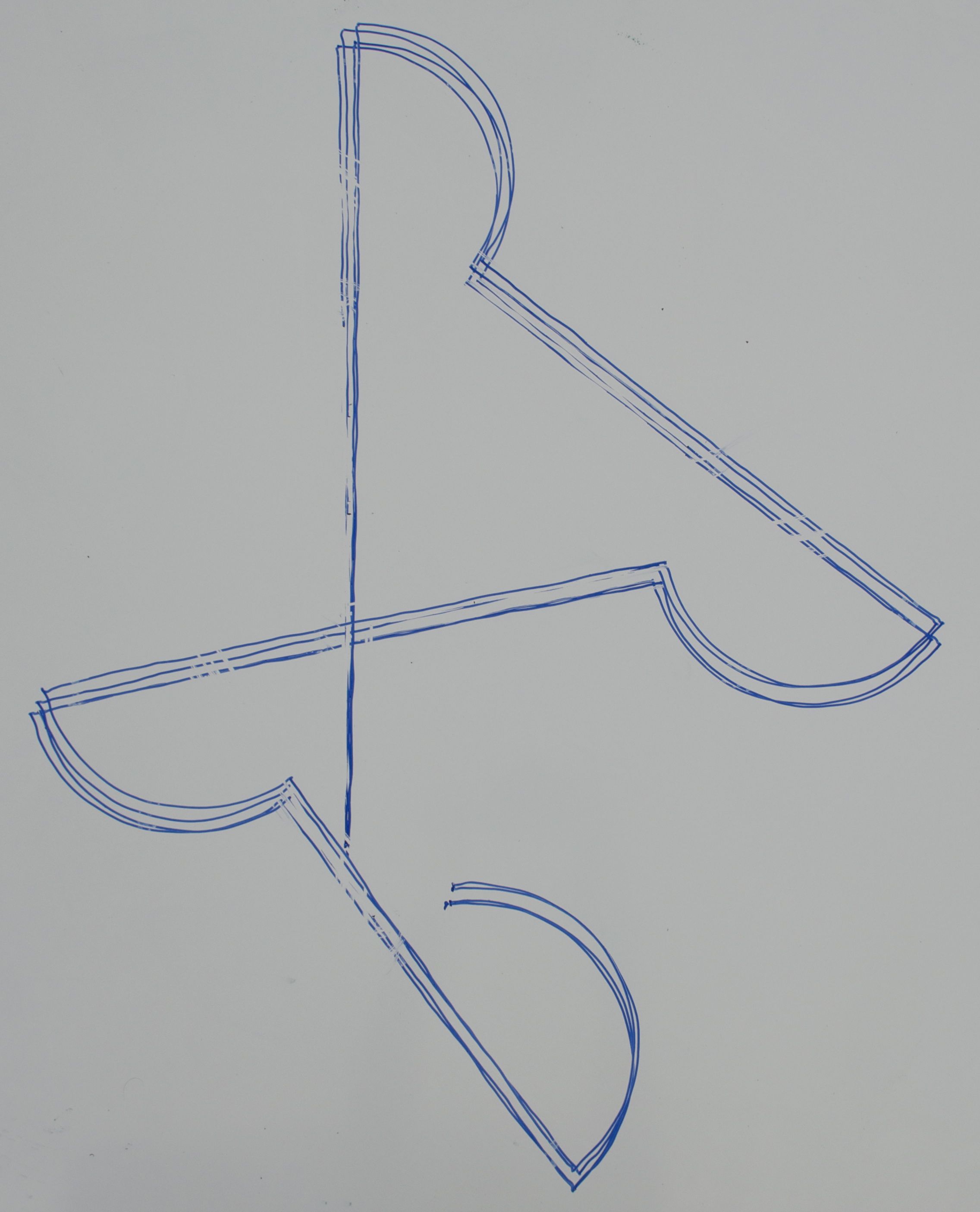
We used Maja Mataric’s low-fi approach to gathering data on the movement of robot [3] by strapping a whiteboard marker on the front of it and running it on a whiteboard. The result after three runs can be seen in the picture below.

The lines drawn by the robot after three runs

The lines drawn by the robot after three runs

As can be seen from the picture, the robot ends up almost at its starting point. However, the angles turned were not quite right which resulted in the deviation from the starting point. We were aware that this might happen before we began as we had made similar observations when we were making our contestant robot for the Alishan track competition in Lesson 7 [3] where we saw that a command to turn 90 degrees would be off by a degree or two. Brian Bagnall notes this as well, saying Blightbot does a good job of measuring distance but his weakness arises when he rotates. [1]

Avoiding obstacles
After finishing the Blightbot test program above we moved on to try to avoid obstacles in front of the robot when traversing the same path as was used in the Blightbot. To do this we added an ultrasonic sensor to the robot which we used to measure if anything was in front of the robot.
Inspired by an implementation of an EchoNavigator class [4], we used the RangeFeatureDetector class of lejOS which listens for objects within a given distance. When the listener finds an object within this given distance it calls the featureDetected() method which we overrode to turn a random angle either to the left or the right and then move forward a bit. After turning away from the obstacle a bit the robot would then move to the next waypoint on the path while still constantly listening for any objects in front of it.
Before using the RangeFeatureDetector class we tried to implement a method to have the robot stop whenever it saw an object in front of it. This failed as the robot would still see the object when trying to move away from the object and then basically be stuck in stopping in front of the object. The RangeFeatureDetector has the enableDetection() method which easily allows for turning the detection of objects on and off which remedied this problem.

Below is a video of the robot traversing the short path while detecting objects, or it can be watched here.

Calculating pose
In [5] the pose of the robot is calculated after every movement of some delta distance while in [6] the pose is updated every time some delta time has passed. Furthermore [6] uses a formulae for calculating the pose when moving in an arc which is different from the formulae used when moving straight, where [5] doesn’t distinguish between the two. When it comes to accuracy [5] is more accurate as long as the delta distance is smaller than the delta time for [6] makes the robot move. It should also be mentioned that the formulae used in [6] for calculating arc er more precise as they take in to account the angular velocity into account which at least in theory should be more precise, depending the delta time.

The LeJOS software of the OdometryPoseProvider-class uses [6] in the sense that it distinguish between driving straight and in arcs. Also the calculation of the new pose is triggered by calling the updatePose-method with some Move-event-object, which can either be created at a certain time or distance moved. We haven’t be able to find if it time or distance that triggers the creation of Move-event-objects. Depending on how the sampling interval it could be beneficial to decrease delta for more samples and get a more precise read-out. But it should be also be noted that depending on how you measure the distance travelled since the latest event might become a problem if the values becomes zero if i.e. it’s the tacho counter of the motors, because then the pose might not be right at all. The updatePose-method code can be seen below.

updatePose-method

Code from the updatePose-method in the OdometryPoseProvider-class of the LeJOS API

Conclusion
As we noted above, the object-avoiding robot skips to the next waypoint when it encounters an object. An interesting further development could be to have the robot try to find a way around the object and make it to the intended position before moving on to the next waypoint.

Reference
[1] Brian Bagnall, Maximum Lego NXTBuilding Robots with Java Brains, Chapter 12, Localization, p.297 – p.298.
[2], Maja J Mataric, Integration of Representation Into Goal-Driven Behavior-Based Robots, in IEEE Transactions on Robotics and Automation, 8(3), Jun 1992, 304-312.
[3] http://bech.in/?p=205
[4] http://fedora.cis.cau.edu/~pmolnar/CIS687F12/Programming-LEGO-Robots/samples/src/org/lejos/sample/echonavigator/EchoNavigator.java
[5] Java Robotics Tutorials, Enabling Your Robot to Keep Track of its Position. You could also look into Programming Your Robot to Navigate to see how an alternative to the leJOS classes could be implemented.
[6] Thomas Hellstrom, Foreward Kinematics for the Khepera Robot

Lesson 8

Date: 18th of April 2013
Participating group members: Kenneth Baagøe, Morten D. Bech and Thomas Winding
Activity duration: 6 hours

Goal
The goal of this lab session is to construct a robot for the Lego Sumo Wrestling contest as described in the lesson plan.

Plan
The plan is first follow the instruction in the lesson plan and then improve the robot to increase our chances of winning the contest.

Progress
Construction and first observations
We started out by constructing the robot as described in the lesson plan, pictured below.

Sumo Wrestler - basic setup

Sumo Wrestler – basic setup

Next, we installed the basic program on the robot and tried running it in the arena. Below is a short video of it, showing the behaviour of the robot when running in the arena without an opponent, can also be viewed here: http://youtu.be/7NbRPb7FulY.

From observing the robot running the program we saw what we expected to be two triggers: When the robot saw the white edge on the arena and every five seconds, these can also be seen in the video above.

The behaviour of the robot wheen seeing the white edge is that it backs up a bit and then turns, where both the backwards distance moved and the angle turned are constant. The behaviour related to the trigger that happens every five seconds is that it turns, this time the angle of the turn is random. Finally when none of the two mentioned triggers were triggered the robot would simply move forward at full speed.

The SumoBot code
Looking into the code we found that the structure of the lower and higher levels of control can be depicted as seen in the figure below.

Control levels for the basic SumoBot

Control levels for the basic SumoBot

This means that the drive function is the lowest priority of the behaviours of the robot, whenever a trigger is triggered the drive behaviour will be suspended. The second-lowest behaviour is the turn behaviour which turns the robot in place, this behaviour can be suspended only by the edge avoiding behaviour. Finally the highest priority behaviour of the robot is avoiding the edge, being the highest priority means that it can never be suspended and will always take precendece over any other behaviour.

Taking an example from the code, the turn behaviour is implemented with the following code.

The main part of the Turn behaviour code

The main part of the Turn behaviour code

As can be seen our assumption that the turn behaviour happened roughly every five seconds was correct as there is a delay of 5000ms. When the turn behaviour starts actually doing something, that is, when the delay has been completed, it starts by suppressing the behaviour that has priority right below it. This is then followed by the functions that makes the robot turn a random angle. Finally the behaviour releases the suppression on the behaviour that it suppressed when it started.

This basic idea of “suppress behaviour below in regards to priority – execute behaviour – release suppression” is used in all the behaviours in the SumoBot and should make it fairly straightforward to add extra behaviours to the robot.

The way that each behaviour knows what to suppress is implemented in the abstract class Behavior.java where the constructor asks for a behaviour. This provided behaviour is then treated as the one right below in a subsumption architecture. If one should be interested in creating a new lowest priority behaviour, it should be noted that the lowest priority behaviour is simply provided null as its subsumed behaviour.
When a behaviour receives a subsumed behaviour it creates a SuppressNode which, in its essence, contains a counter for the number of times it has been suppressed. When a behaviour suppresses another behaviour the suppress cascades down the subsumption architecture, basically incrementing the suppress counter for every lower priority behaviour by one, and vice versa for the release function.

The suppress() method

The suppress() method

The function of the SuppressNode is then to tell whether or not a behaviour is suppressed which is determined by the simple function of whether the suppress counter is zero or not.

The isSuppressed() method that determines whether a behaviour is suppressed or not

The isSuppressed() method that determines whether a behaviour is suppressed or not

OverturnOpponent/Improving the SumoBot
After finishing construction of the base SumoBot we started adding the functionality for overturning an opponent in the arena, we went about this by adding a supersonic distance sensor to the robot to determine whether there is something in front of it and adding a forklift arm to do the overturning.

Our first attempt was following the extension guide for the base car to add the forklift arm and the supersonic sensor to build a robot that looked like the picture below.

First attempt

First attempt

This way of constructing the robot, however, presented a number of problems: The forklift arm was not very rigid, owing to the fact that it was only secured in one side. The forklift arm could also not be lowered all the way to a horizontal position because it would hit the light sensor. Finally the supersonic sensor could not always be used to detect whether there was something in front of it since it was mounted to point straight ahead. Testing against the base car which is not very tall we found that the sensor would not pick up the opponent at all.

The above things taken into consideration we rebuilt the extensions somewhat to remedy the problems. This meant that we moved the forklift arm forward a bit so it would not hit the light sensor, secured the arm on the other side of the robot to stabilize it and tilted the supersonic sensor downwards so it could pick up objects in front of it that were short.

The modified SumoBot

The modified SumoBot

This construction worked well as all the problems described above were resolved: The arm could now lower all the way to a horizontal position, it wasn’t as wobbly and the supersonic sensor could be used to detect smaller robots in front of it.

A final problem was that the even though the forklift was now pretty rigid and more sturdy than the first build, the motor that controlled it was not strong enough to actually lift an opponent robot. We tried to remedy this by gearing the forklift motor up but that still did not output enough power to lift another robot. We also noted found that the distance sensor was angled too much downwards to properly detect opponents, therefore we angled it just a bit more up which made the detections of opponents more reliable.

The finished Sumo Wrestler

The finished Sumo Wrestler

The Forklift behaviour
As we added a new functionality to the robot when we added the forklift arm, we had to add a new behaviour. This behaviour would utilize the forklift arm to try to overturn the opponent when the robot detected the opponent by way of the supersonic sensor.

The behaviour was implemented in Forklift.java, the main part of the behaviour is pictured below (where uss is the supersonic sensor and motor is the motor that controls the forklift arm).

The Forklift behaviour

The Forklift behaviour

The behaviour checks the distance until it finds something less than 15 cms away from the robot, when this happens the robot suppresses the lower prioritized behaviours, raises the forklift arm and moves forward at full speed for two seconds and then lowers the arm again, followed by releasing the suppression.

When programming this behaviour we did not implement a functionality to suppress the access to the motor that moves the forklift arm as we knew that only a single behaviour would be accessing it. This is important to keep in mind should we ever want to expand upon this program since it would create problems if we tried to access the motor from multiple behaviours.

We added the forklift behaviour as the second-highest priority for the robot (SumoBot.java), leaving the avoid-edge behaviour as the highest priority. This gave us the levels of control depicted in the figure below.

Control levels

As we were adding the forklift behaviour we also wrote another behaviour that could possibly be used in lieu of the forklift. This behaviour (Ultrasonic.java) would simply move the robot forward at full speed when something was detected in front of the robot.

Conclusion
As noted above, even when gearing up the motor that controls the forklift arm it did not output enough power to actually lift another robot. We don’t know whether it’s possible to add further strength to the arm, but it seems to be necessity to actually be able to overturn opponents. Otherwise a different approach to the SumoBot could be the “move-forward-when-opponent-detected” behaviour that was described above. This approach would simply attempt to push the opponent out of the arena instead of flipping him over.

Heartbeat service setup on Linux

In this blog I’m going to tell you how to setup heartbeat service on your machine to keep track if it up and running or for how long it has been down. To see if your machine is running or how long time since it made its last beat you can go to http://services.bech.in/heartbeat/. In order to add your server to the list please contact me and I will provide you with an ID.

For this to work the server needs the Java Runtime Enviroment (JRE) or some sort that being Oracle JRE or OpenJDK. You are going to need two files: script.sh and Beat.class. You can download them into using the following, it is important that you place them into the correct folder so the first change directory need to be right or it will not work!

cd ~/
wget http://services.bech.in/heartbeat/script.sh
wget http://services.bech.in/heartbeat/Beat.class

Next up we need to create the log-file there errors are write if any happen. To create the log-file use the touch-command:

touch heartbeat-log.txt

Now there are to things we left we need to do, first we need to edit the script to use your machine’s ID, so open the script.sh-file with you favorite text-editor and change the #Your ID# to the ID I have provided for you. If the ID is abc123 the line in the script.sh-file should look like this:

java Beat abc123

The finally thing we need to do is to add a cron job to the crontab of Linux, to do this simply open the crontab with the following command:

crontab -e

If it is the first time you use it will ask to select a text editor. Now add the following line to end of the file on a new line:

*/1 * * * * ~/script.sh | tee -a ~/heartbeat-log.txt

Save and close the file and you should get a response from cron like:

crontab: installing new crontab

Now go to http://services.bech.in/heartbeat/ to see if your machine is able to make a ping else consult the log-file. The page automatically updates every 10 seconds and the beat is made every minute with the above cron job.

Setting up network connection on NFIT cable network from Ubuntu CLI

First you need to register your MAC address to be able to use the cable network at NFIT. The simple solution is to send a mail to Michael Glad with our MAC-address and NFIT username if you already know the MAC address. However if you want to help yourself and lighten the workload on Michael Glad you simply setup a DHCP-client on your server and register using a web browser. In the case that you installed Ubuntu server where there isn’t any default web browser installed and you are limited to text versions like Lynx. It should be noted that as long as you haven’t registered your device you wouldn’t be able to do anything outside of the LAN, this means no apt-get or alike! So therefore you can’t even install Lynx that way around. First of you need to setup the DHCP-lease and be able to ping your default gateway or Google DNS (that service is open).

If there is only a single NIC this fairly simple – the reference you need for the first part is namely “eth0”. However with multiple NICs and maybe even multiple ports per NIC, this becomes a little more tricky. The way to solve this is to use some of the basic tools available, in this case the lshw command. Depending on how many NICs and ports your machine has it might be a good idea to pipe the output into a separate file as it might not all fit into one screen. So first of you need to connect the network cable to the machine and then execute the following command in your terminal:

ip addr > network.txt

This will take the standard output from the command and write it to a file instead of displaying it on the screen. Next up we will need to find the line there says that the port is physically UP, it looks something like:

2: eth0: mtu 1500 qdisc pfifo_fast state UP qlen 1000

Now that we know which reference we need, e.g. “eth0”, we can edit the interface setting of your system. This is done in the /etc/network/interfaces-file. Use any text editor to edit the file, i.e.:

vi /etc/network/interfaces

Add the following code to the file if the reference is “eth0”, otherwise change of a different reference:

auto eth0
iface eth0 inet dhcp

Finally to get a DHCP-lease you need to restart your network module of the server which can be done with the following command:

sudo /etc/init.d/networking restart

When the restart is complete you should be able to ping the default gateway and/or Google DNS (8.8.8.8 or 8.8.4.4). Next you need to install some text based web browser like Lynx, this requires you to have a internet connection on some different machine and a USB-stick. You need to download a .deb-file of Lynx which can be found at http://pkgs.org/ubuntu-12.04/ubuntu-main-amd64/lynx-cur_2.8.8dev.9-2_amd64.deb/download/

Now download the file and transfer it your USB-stick (has to be FAT or alike for your Ubuntu Server to be able open it). To access the USB-stick on the server you first need to mount which requires a little work:

sudo mkdir /media/external/
sudo mount -t vfat /dev/sdb1 /media/external -o uid=1000,gid=1000,utf8,dmask=027,fmask=137

The code above assumes that USB-stick in the sdb1 in dev and that it uses a FAT filesystem, if this is not the case please consult the Ubuntu Help pages. To unmount the USB-stick again use the following command:

sudo umount /media/external

Now copy the .deb-file on to the server, i.e. your home folder, and execute it:

cp /media/external/lynx.deb /home/rewt/lynx.deb
cd /home/rewt/
sudo dpkg -i lynx.deb

Now that you have install Lynx all you need to do is start with some random target like Google and follow the instruction on the screen from NFIT.

lynx google.dk

After the recommended reboot of the system should you now be able to go any website with Lynx, use apt-get and other services.

Lesson 7 – Update 2

Date: 15th and 16th of April 2013
Participating group members: Kennekt Baagøe, Morten D. Bech and Thomas Winding
Activity duration: 4 hours

Goal
To make the robot drive the rest of the way of the Alishan track, as described in the previous post, we have already reached the top, but have not made it back down.

Plan
Continue our where we left off at “Update: Lesson 7”, and start by making a simple inverse of the uphill program to make it go downhill.

Progress
As mentioned in the previous blog, Update: Lesson 7, we had a 90% chance of getting the robot to drive all the way to the top of the track and turn 180 degrees there. The trip takes around 18 seconds which is relatively slow, which is most likely due to the way we handle the corners in a “stop at first corner – turn – move – stop – turn – move up next slope” way instead of a continued motion.

When we arrived at Zuse Monday someone had moved the track into a different room, and unfortunately this has made the track a little different from when we were testing on it on Saturday as most of the slopes are now crooked. The changes made it very hard for us to make the robot drive all the way to the top as the crooked nature of the slopes meant that the robot would drift either left or right when it was supposed to move straight ahead. We had some success, but we were reduced to a chance of 30-35% of reaching the top every time.

So when we reached the top we had hope that the robot would make it downhill correctly, which it unfortunately didn’t and we had to apply some small changes to our downhill algorithm, first error was not to listen for the first black line seen but it should be the second instead which made the robot turn right right after it left the top. Finally we had to adjust the angles to turn and length to be driven, but with the low chances of getting to the top from the starting point, it took a lot of time to see if the changes we made were correct or not.

Another change we made was not to drive by distance on the plateaus but instead looking for lines in the hope of making the line of attack of the next straight run more precise. However this didn’t work that well either. One of the reason for that was that even now we place in almost the same position at the start point it didn’t see the line in the same place on the plateau every time. Basically we couldn’t drive in a straight line and as mentioned in the previous post, Update: Lesson 7, we tried to overcome this by getting two motors which match each other well in terms of speed and rotational accuracy, but this did not solve it because of the crooked slopes as mentioned earlier.

Finally we had a run where the robot got almost all the way to the finish as well – unfortunately it drove off the side on the last straight stretch, but it did manage to touch the green part with one wheel and color sensor which made it stop. After several attempt afterwards to replicate the run with a small change for the last straight stretch we throw in the towel and wouldn’t have a time for the contest. Unfortunately we were not recording when we got this best attempt at completion. The video below is how far we managed to get when recording.

Conclusion
In theory the sequential solution should be the fastest way to do complete the track, however it relies on so many variables, like the mentioned moving of the track and subsequent crooked slopes, it becomes very hard to implement and we had to spend a lot of time on small details which we might have been able to avoid using, eg. a line following robot instead or if we had been able to get a reliable heading which we tried to do with the sensors mentioned in the post Lesson 7.

Lesson 7 – Update

Date: 13th of April 2013
Participating group members: Morten D. Bech and Thomas Winding
Activity duration: 8 hours

Goal
To continue our work on the Alishan train track contest robot.

Plan
As the building of the robot was completed Thursday the 11th of April, the software is now the only missing part. On Thursday we tried out some smaller things that we should be able to use for the run, like a 90-degree turn and moving forward until a black line is detected.

Our plan for the program is to make a simple sequential program that uses input from the two light sensors. We aren’t going to follow the line using a PID-control as we hope a “free-running” robot should be faster.

Progress
First off we did not have the code examples from Thursday because they were made on Kenneth’s laptop, who was not able to be present today, but luckily they weren’t too hard to remake – we need a common repository for sharing and saving files. After we recreated the examples, we made a small program for showing the light values of the two mounted light sensors. With this program we then measured the light values of white, black and green surfaces in the necessary corners of the track. We know that daylight affect the readings but it still gives us some idea of the range that our threshold should be in.

After some serious trouble with getting the robot to stop when seeing a black line using the light sensor we ended up solving the problem by using the stop() method instead of the quickstop() method from the DifferentialPilot-class in the LeJOS API, we’re not sure why but the quickstop() method does not seem to work. Next up we tried to use the light sensor to detect other lines to decide if, and when, the robot should turn, however we found that too imprecise and therefore changed our method when moving in the hairpins to be detect black line – turn 90 degrees – move a certain distance using the travel-method from the DifferentialPilot-class – turn 90 degrees – move towards the next hairpin and repeat the cycle.

Even after changing the algorithm of the robot we still weren’t able to complete the second hairpin – the reason being that the robot simply couldn’t drive in a straight line. To that end we found that there were two parameter on the robot we could adjust: The first one is the rear wheel and the second are the motors. The first parameter we tried to adjust by changing the rear wheel to a different wheel setup which can be seen on the picture below. Changing the rear wheel setup only made things worse as the robot became more unreliable in its ability to drive straight and we changed it back to the original setup.

Alishan robot backend

Alishan robot backend

With regards to the motors we found a webpage [1] which explained how to find two motors with almost identical power output and rotational accuracy. After consulting the webpage we found two motors which seemed to be almost identical. This helped a lot and, after mounting these motors, the robot could now move up the slopes with no difficulties, it didn’t get it right a 100% of the time but somewhere around a 80-90% success rate. We made a small video of the robot going uphill which can be seen here or below. There is still room for improvement, but we would make a complete run of the first half of the track before we started optimizing.

Backlog
We still need to make the sequential commands for driving downhill and optimize so we reduce the time it takes to complete the track. One possible optimisation we found was to use an travel arc-method in the DifferentialPilot-class, which moves the robot in an arc, instead of the current solution of turn – move – turn.

Reference
[1] http://www.techbrick.com/Lego/TechBrick/TechTips/NXTCalibration/

Lesson 7

Date: 11th of April 2013
Participating group members: Thomas Winding, Kenneth Baagøe and Morten Djernæs Bech.
Activity duration: 7 hours

Overall goal
To build an autonomous Lego car that can complete the Alishan train track as fast as possible using Lego NXT.

Overall plan
First of all, we’ll build a foundation for the car which has the lowest possible centre of gravity.
We’ll try different types of sensors: compass, gyro, lightsensors – testing which will be the most useful in this particular assignment. We will attempt to construct the car in such a way that we have the most control when turning left or right.

Todays work
We’ve build the foundation of the car. The wheels are placed with the largest possible distance between each other, making the car turn with a big radius. This gives us the most control of the turn as possible. Each wheel consists of two of the large wheels (81.6mm diameter) next to each other for a larger amount of friction as the car will be moving uphill during the final test. Two light sensors have been mounted on the front of the car for detection of the black line on the train track.

DSC_0062

DSC_0061

Codewise, we have been able to make the car turn 90 degrees in both directions using the rotate() method in the DifferentialPilot class in lejOS. This did require a bit of trial and error as a call to rotate 90 degrees would cause a turn that was a bit over 90 degrees.
We are now using Bluetooth to upload programs to the NXT brick straight from Eclipse – making it easier when we are running code as attaching the USB cable is not required. This involved a bit of fiddling too, seeing as Eclipse attempts to upload the program to the brick that is first on the list of the discovered Bluetooth NXT bricks.

Video of the car turning

Video of the car driving forward

Testing various sensors
For directing the car we tested two different sensors so far: The compass sensor and the gyro. Both unfortunately presented some problems which means they will most likely not be used.

The compass sensor
This sensor was the first we tested. The idea was that we would measure the length of the slopes and the plateaus of the track and simply have the robot travel these distances while correcting itself according to the compass sensor. Basically the starting heading of the robot would be declared as the 0 degree heading and it would keep this heading until it would reach the plateau, do a 90 degree right-turn, travel the length of the plateau and do another 90 degree right-turn. Following this it would now have to follow a 180 degree heading up the second slope and so on.
Unfortunately the compass sensor proved to be very unreliable as sometimes a small change in the actual heading would cause large differences in the measurements of the sensor, a 1-2 degree turn could be measured as a change of up to 40 degrees in heading. Some research into the sensor also provided the information that it is very susceptible to interference from any object that has, or generates, a magnetic field. These objects could simply be nearby metal, but the motors and the NXT brick also generate magnetic fields when running which is most likely what interferred with our measurements as the sensor was quite close to both.

The gyro
The second sensor we tested. As we saw that the lejOS library had a DirectionFinder class based on using a gyro which could also measure degrees, this seemed like a solution akin to what we were trying to do with the compass sensor but less susceptible to interference.
Using this sensor was a more stable approach compared to the compass sensor but we encountered another problem with this: The gyro would, seemingly randomly, start drifting heavily in measurements, upwards of 2 degrees per second. We’re not sure if this is a general problem with gyros or the one we had. Looking into the source code for the gyro direction finder class we noted that it did take drifting of the sensor into consideration as it tried to compensate for it. We tried increasing this compensation by up to 10 times its original value but, unfortunately, to no avail as it would still drift and at this point the correction started affecting the measurements.

Lesson 6

Date: 14th of March 2013
Participating group members: Thomas Winding, Kenneth Baagøe and Morten Djernæs Bech.
Activity duration: x hours

Overall goal
To build various Braitenberg vehicles, using Lego NXT, and observe what behaviours they exhibit when e.g. exitatory and inhibitory connections are used.

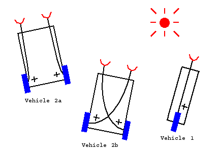
Figure 1

Figure 1

Overall plan
To achieve the goal mentioned above, we will be drawing inspiration from the lesson description and Tom Deans notes[1][2]

Braitenberg vehicle 1
Goal
To make vehicle 1 as pictured in Figure 1.

Plan
As a sensor for the Braitenberg vehicle we will be using a sound sensor. First we will try mapping the values measured to a power between 0 and 100. Afterwards we will try mapping the values to a power between -100 and 100. Lastly we will try mapping the power an inhibitory connection instead of the exitatory we will be using to the two first experiments mentioned.

Results
First experiment: Using raw values from the sensor we map to power in a simple way: Since the sensor measures values between 0-1023 we divide the value by 10 to get an approximate value between 0-100 and round down/up in case the value should be outside the 0-100 range (in this case the values could only happen to be over 100 though since the lowest measure is 0). Using these values we get a robot that moves forward when it registers some sound. This sound has to be of some volume though, since the motors do not run unless they get a power of somewhere around 50-60 or above.

Second experiment: We use the same procedure as above except to get the motor power we do the following calculation on the sensor value: (soundValue/5)-100 to get values in the range [-100, 100]. The resulting behaviour in the robot is that it moves forward when it registers sound and backwards when it doesn’t

Inhibitory connection: We achieve the inhibitory connection simply by inverting the sensor value compared to the one used in the above experiments. The resulting behaviour in the robot is the opposite of the above results.

Braitenberg vehicle 2
Goal
To make vehicle 2a and 2b as pictured in Figure 1 and run them with both inhibitory and exitatory connections.

Plan
We will mount two light sensors on the vehicle and map motorpower to the wheels. This will be done in two ways as the figures (2a and 2b) in Figure 1 show, which means we will try with the sensor value being mapped to power on the wheel placed diagonally across or to the wheel on the same side as the sensor.

Results
Running the robot with the sensors controlling either the wheel diagonally across from them or the wheel on their side results in two behaviours: If they control the wheel diagonally across the behaviour of the robot is that it moves towards light and if the sensors control the wheel on their own side, the robot moves away from light.

Braitenberg vehicle 3
Goal
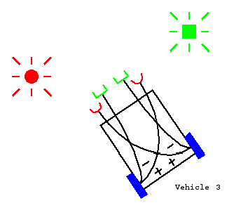
Build vehicle 3 which is pictured in Figure 2. The vehicle should be able to move between a light source and a sound source using its different sensors.

Figure 2

Figure 2

Plan
To detect the light source and sound source we will use sound and light sensors.

Results
We haven’t made the code for the robot yet, so it’s going to subject for another blog post soon.

References
[1]Tom Dean, Introduction to Machina Speculatrix and Braitenberg Vehicles
[2]Tom Dean, Notes on construction of Braitenberg’s Vehicles, Chapter 1-5 of Braitenbergs book

Lesson 5

Date: 7th/12th of March 2013
Participating group members Thursday: Thomas Winding and Kenneth Baagøe.
Participating group members Tuesday: Thomas Winding, Kenneth Baagøe and Morten Djernæs Bech.
Activity duration:
6 hours Thursday 7th of March 2013
3 hours Tuesday 12th of March 2013

Overall goal
The overall goal of this lesson is building and programming a Segway-inspired self-balancing NXT robot.

Overall plan
To achieve our goal we will use the information provided here:

Self-balancing robot with a light sensor
Goal
To build a self-balancing robot that will adjust its balance according to measurements from a light sensor.

Plan
We will build a robot inspired by Phillippe Hurbain [1] and run the program made by Brian Bagnall [2] on it. Furthermore we will try to adhere to the guidelines that Phillippe Hurbain propose and observe whether that helps on the operation of the robot.

Result
The robot tips over very easily, even when we tried in a dark room on a non-uniform surface as suggested by Phillippe Hurbain. There are two major influences on this: Phillippe Hurbain suggests starting the program when the robot is perfectly balanced. Attaining a perfect balance is hard to do when simply starting the program by hand, even pushing the enter button on the robot will bring it at least somewhat out of balance and thus skew the measurement that the robot balances by. Besides the aforementioned the program is also configured to Brian Bagnalls hardware and we suspect that there might be subtle differences compared to ours, which could cause problems in the balancing.

Changing the values of the parameters from a PC
Goal
Changing the values for the PID controller in the program mentioned above, from a PC via a GUI.

Plan
Drawing inspiration from the provided BTcontrolledCar and PCcarController programs, we will program a GUI that is able to take input from a user and supply these values to the PID controller.

Results
Using the GUI to provide new values for the program over a Bluetooth connection works fine, there are, however, some shortcomings in the program that we hoped to implement, but haven’t. One thing we might implement later is the ability to change the different values for the PID controller on the fly instead of having to restart the program on the robot every time a change is wanted.

Changing the values of the parameters from a PC revisited
Revisiting the shortcomings mentioned above, a program for the robot, which is able to change the kP, kI, kD and scale values on the fly has been made (BTbalance2.java). This operates over Bluetooth and works in tandem with PCcarBalance.java Standard values are the ones provided by Brian Bagnall. To ease calibration of the robot, a three second grace period was added after pressing the enter button which is signaled first with two beeps and lastly a beep sequence to signal the start of the balancing. Furthermore the offset, set by the calibration, is changeable by pressing the left button (decrease) and the right button (increase). However, when exiting the program via a press on the escape button, the robot writes out a large amount of exceptions, the cause of which we were unable to locate.

Running this program on the robot and trying different values for the PID controller, we were able to get the robot to balance for 10-20 seconds on a white surface in a room lighted with fluorescent light. One of the better runs is demonstrated in the video below (values used were: Offset: 542, kP: 53, kI: 2, kD: 36, scale: 18). The fluorescent light did cause some trouble in that the robot would cast a shadow which moved when the robots position changed in comparison to the lights. This meant that it would sometimes recieve a very different reading if the robot moved so that the shadow no longer was where the light sensor measured. We remedied this by running the robot in a dark room where we could sometimes achieve a balancing time of 30-40 seconds.

Self-balancing robot with gyro sensor
Goal
Balance the robot, with the same design used in the previous exercises, using a gyro sensor.

Plan
Follow the AnyWay NXT-G code and translate it to Java.

Result
After translating the NXT-G example to Java, the program unfortunately did not function properly as the robot would instantly move forward at full speed when started and thus tip over.
We will continue on this assignment on Thursday 14th of March 2013.

References
[1] http://www.philohome.com/nxtway/nxtway.htm
[2] http://variantpress.com/books/maximum-lego-nxt/