Lesson 4

Date: 28th of Februar 2013
Participating group members: Thomas Winding and Morten D. Bech, and Kenneth joined us one hours into the exercises Thursday, and everyone was there Saturday.
Activity duration
Thursday 3,5 hours
Saturday 5,0 hours

Overall goal
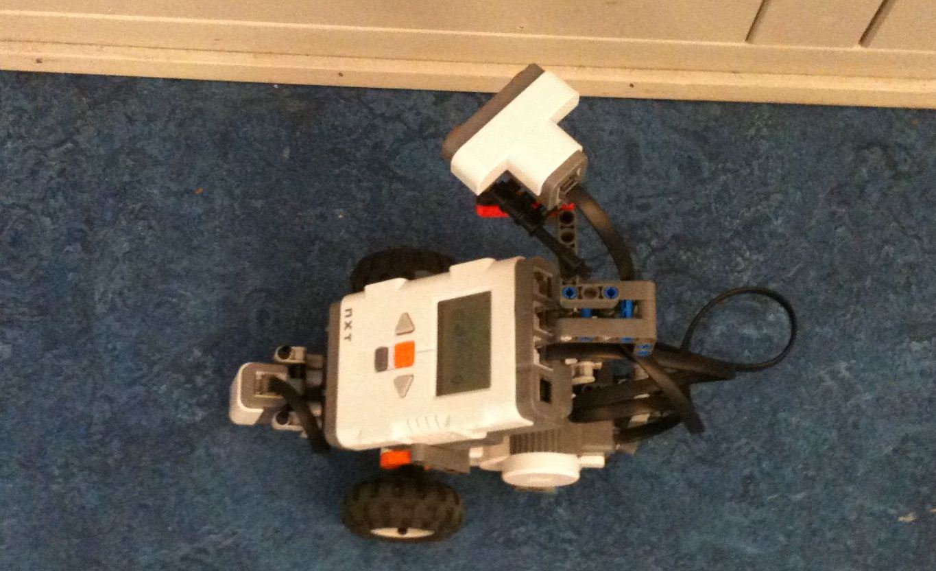
The overall goal for this lesson is to make a black line following robot using a light sensor and a PID control algorithm. The robot should be able to detect the color green and stop if it does.

Overall plan
To complete our goal we will follow the instruction in the lesson plan which is available here.

Black/White Detection
We would like to know what kind of values our light sensor detects for different light and dark areas, and what values different colors are measured as. As a small extra exercise we would like to see how our measurements compare to the ones we did in our first lab session.

Plan
We already the light sensor mounted on the robot from the previous weeks, which means that we simply have to do the measurements. As Ole recommended using raw values from the sensor instead of the percentage values normally measured by using the readValue() method on the sensor, we will be changing the program to do that. We will, however, do a measurement of the percentage for the comparison mentioned above.

Result
The measurements we obtained from the sensor was:

Color Percentages Raw value
White 57 431
Black 38 625
Green 44 573

Conclusion
The values we got this time differ slightly from the values we obtained at the first lesson, but we assume that is because that the cause of that is that we placed the light sensor at a somewhat large distance in the first lesson.

Line Follower with Calibration
The goal here is to get familiar with the program LineFollowerCal and determine how the it works.

Plan
To accomplish our goal we will at first have a look at the supplied program and try to determine what it is supposed to do. Afterwards we will upload it to our robot, run it and observe what happens.

Result
After reading the code we had a rough idea that the robot would most likely behave like a bang-bang robot. We uploaded the program to the NXT and ran it. We captured the performance of the robot in a small video which is available here or you can watch it below.

Conclusion
As we expected the robot did have the behaviour of a bang-bang robot, that is, the values for white and black are stored first, a threshold is calculated and the robot then moves forward while turning right/left depending on whether it measures a black or white value.

ColorSensor with Calibration & Line follower that stops in a Goal Zone
We want to extend the functionality of the Line Following Robot to include detecting the color green. When detecting the green color robot should stop.

Plan
To add the new need functionality we have created a class called ColorSensor as suggested in the lesson plan . We took a lot of the functionality from the BlackWhiteSensor class into the new class and added a new variable green for calibrating the value of green. Furthermore we need to add a boolean method akin to the black() and white() for checking if the sensor sees green.

Result
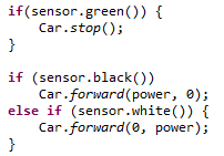
We made the needed changes to the program and found that we had to change the decision algorithm of black and white a bit. The change needed was that if the sensor sees green it can’t see white or black which is illustrated below.
bw-green
A video documenting the robot in action was recorded and is available here or can be watched below.

Conclusion
With some small modifications to the code of when we detect black and white, and letting the detection of green be an interval of 40, it worked smoothly. For the interested reader the code of the ColorSensor-class is available here. The change to the LineFollowerCal-class was to include a new else if clause in the while-loop to ask if sees green and then stop the motors.

PID Line Follower
Expanding on the line follower using the light sensor, we are going to use the light sensor to write a line following program for the robot again, this time with PID regulation.

Plan
We are going to implement the parts of the PID regulation one by one, starting with the proportional control, then the integral and finally the derivative. After implementing each part, we will also run the program on the robot to make sure that it is functional.

Results
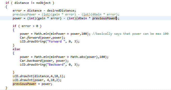
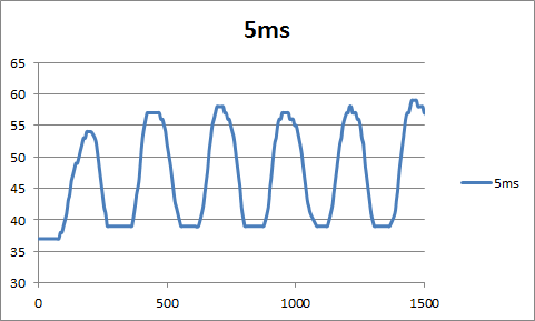
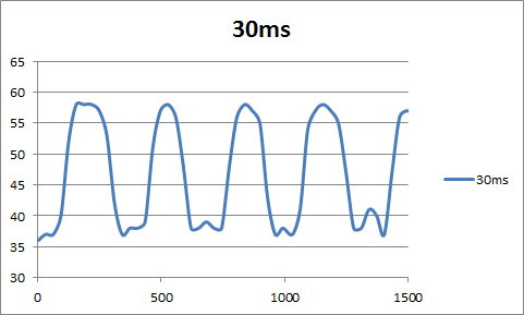
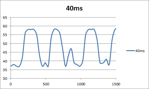
We implemented our PID Line Follower base on [1] is note upon the subject. We started with the P-term and got that to work fairly quick. However when we tried to implement the I-term the robot quiet quickly began to spin around the line, but then after implementing the D-term it stopped to spin around and instead began to follow the line. Finally we tried to tweak the constant values so that the robot would follow the line more smoothly, however after about an hour the results weren’t improving and we stop. When tweaking the constants we sometimes experienced that robot had a very hard time following the line in very sharp corners.

We made a small video clip of the robot which is available here or can be seen below.

Conclusion
As can be seen in the video clip the robot oscillates quiet a bit, and as mentioned earlier we had quiet some trouble with tweaking the constants to improve the performance of the robot.

The class code is available here.

Color sensor
The final task at hand is to construction/implement a program which using a color sensor follows a black line and stops when it sees green.

Plan
Our plan is to use a simple bang-bang algorithm with the output color from the sensor to decide the direction and speed of the robot. We are going to try smooth the curves by having five intervals or colors that we work with that is black, dark gray, gray, light gray and white. Finally if the color is green we stop the robot.

Results
The implementation was quickly in place, however we had a lot of trouble with how to use the color sensor correctly in the implementation. Fortunately we found this example which was a lot of help.

After a minor change to the code it worked very well as can be seen from the video clip below or here.

Conclusion
As can be seen in the video clip the robot work nicely but we haven’t implemented using a PID control as we get a RGB vector or a color ID back from the sensor and the easiest way for us to implement it was the color id.

The class code is available here.

Status
We had some trouble with tweaking the PID controller correctly and therefore we need figure out how to get that done correctly. This is very important for the next weeks Segway robot which is an inverted pendulum.

References
[1] A PID Controller For Lego Mindstorms Robots

Lesson 3

Date: 21st of February, 2013
Participating group members: Kenneth Baagøe Kristiansen, Morten Djernæs Bech, Thomas Winding
Activity duration: 5 hours

Overall goal
The overall goal of this lesson is to familiarize ourselves with the NXT sound sensor by doing the exercises described here.

Exercise 1
Goal
The goal is to mount the microphone sensor and try to see how it works.

Plan
Follow the instruction on how to mount the sensor in manual and upload program, and try with sound levels and distances.

Result
A loud sound very close the sensor gives us a reading of 90. A similar loud sound at half a meter gives us reading between 20 and 50, it differs a lot.

Conclusion
Very close to the sensor the read outs are pretty constant, the further away from the source of the sound, the lower the read outs, while also varying a lot more.

Exercise 2
Goal
The goal in this exercise is to use a datalogger for saving sound data. Furthermore we will sketch a graph explaining this data.

Plan
Implement the datalogger, implement the SoundSampling.java, and download the sample.txt. Using the data gathered, plot a graph and analyze it.

Result
soundMeasurements
As time passes the robot moves further away from the source of the sound, starting at a distance of 15cm and ending at a distance of 100cm.

Conclusion
As can be seen from the graph there is a logarithmic development in the value measured by the sensor. The slight inconsistencies in the values measured can be attributed to ambient noise, like other students talking and experimenting with sounds as well, and the fact that we moved the robot manually which means that the velocity away from the sound source was not constant.

Exercise 3
Goal
The goal in this exercise is to make our first application using the sound sensor. We’ll observe how the car responds to shouting and clapping.

Plan
Implement the SoundCtrCar.java and use it with the simple class Car.java.
Test the behaviour of the car and watch what happens.

Result
The car would move around keeping the same direction until a clap or a noise/sound was made loud enough making the car turn the other direction.
A demonstration of the car is shown in exercise 4.

Conclusion
Before running the program, we looked at the code so we had an idea of what it was supposed to do. Testing it, it behaved as we expected, shifting between the different states (forward, left, right, stop) when making sounds that went above the threshold. We discovered that it only reacted to quite loud sounds, basically e.g. clapping had to be done very close to the sensor to get a reaction from the robot. What we didn’t expect was that we were unable to stop the program by any other means than removing the battery.

Exercise 4
Goal
The goal in this exercise create a ButtonListener which listens for the ESCAPE button and exit the program when its pressed.

Plan
Implement the ButtonListener in the car using a simple example from the leJos tutorial. Observe what happens.

Result
We implemented a boolean, called running, in our code to indicate whether or not the program should be running.
boolean

Additionally we added the boolean to the condition for the while loop in the waitForLoudSound() method to make sure the program exits the loop when the escape button is pressed.
soundLevelThreshold

Afterwards we added a ButtonListener to the escape button that switches the above boolean so the program knows when to stop.
buttonListener

This video shows our result which is available on YouTube (http://youtu.be/DFqBGQ9PoaE)

Our modified SoundCtrCar.java: SoundCtrCar.java

Conclusion
As the video illustrates, the behaviour of the program is as followed:
1st clap makes the car start running forward. 2nd clap makes the car turn right until the 3rd clap which makes the car turn left. The car is stopped by the 4th and last clap. With our button listener on the Escape button implemented it is now also possible to actually end the execution of the program as opposed to Exercise 3.

Exercise 5
Goal
Sivan Toledo has investigated how the sound sensor can be used to detect claps.
The goal in this exercise is making the car able to detect claps and compare Sivan Toledo’s method with the one used in SoundCtrCar.java.

Plan
We will implement the methods and observe the car using the different methods.

Result
This video shows our result which is available on YouTube (http://youtu.be/9JpNqvhbjNY).

As can be heard and seen in the video it’s not working perfectly.

Conclusion
The method used to detect claps in SoundCtrCar.java is simpler compared to the method proposed by Sivan Toledo. The method used in SoundCtrCar simply detects a single loud sound and then acts, while in comparison, Sivan Toledo’s method detects an increase in sound by first listening for a lower sound volume, then a high volume, e.g. the clap, and then a low sound volume again.

This difference in the methods to detect volumes means that the robot, with implementations of the two different methods, would have a differing behaviour. With the method proposed in SoundCtrCar, in an environment with a constant loud sound would repeatedly change between its different states (forward, left, right, stop) while, with our implementation of Sivan Toledos clap-detection, it would remain in one state (either forward or stop) since there would be no rises in sound volume.

Exercise 6
Goal
The goal in this exercise is to make the car drive towards the location in which the sound is coming from.

Plan
We’ll mount a second sound sensor to the car, making the car have two, and check where the sound is coming from – turning in that direction.

Result
This video shows our result which is available on YouTube (http://youtu.be/5dJ_PsrVmq0)

Source code for our Party Robot: PartyRobot.java

Conclusion
Having the sound sensors pointing straight forward gave us som trouble making the car follow the claps correctly. This we assume was because both sound sensors picked up the clapping sound and thus had a chance of either continuing to go forward or even turning the wrong way. By placing the sensors at a larger angle away from each other (as demonstrated in the video above), we made the car follow the claps without any trouble, which confirms our assumption.

Lesson 2

Exercise 1:
Goal
The goal of the exercise is to measure the distances that the ultrasonic sensor records with different distances and object/materiales.

Plan
We are going to use hard and soft materiales at different distances and measure the actual distance with a folding ruler.
IMAG0111

Results

Surface Sensor value Actual value
Soft 42 42
Soft 79 78
Medium 80 78
Medium 42 41
Hard 43 42
Hard 78 78

Conclusion
The results contradict our expectations that the softer materiales would resolve in a larger difference between the measured and actual values. We expected that the softer materials would absorb the soundwaves and thus cause readings that would not be as accurate.

Exercise 2
Goal
To see if different sample intervals will affect the distance measured by the ultrasonic sensor.

Plan
The way we are doing to test this by keeping the distance to the object constant and conduct measurements with different sample intervals.

Result
While measuring we kept a constant distance of 17 cm.

Sample interval Measured Distance
0 20
100 20
200 20
300 20
400 20
500 20
2000 20

Conclusion
As can be seen from the results it made no difference using different sample intervals. This means that the old minimum interval is no longer necessary, it might’ve been present in the older versions of lejOS due to the possibility of the sensor receiving an ultrasonic ping which it sent previously and thus getting a wrong reading.

Exercise 3
Goal
Our goal in this exercise is to examine if it’s possible to measure 254 cm and to see whether a lower sample interval will affect the measurement.

Plan
Our plan is to place the sensor towards a wall and move it away from the wall until we get a measurement of 254 cm, once we have that distance we will change the sample interval to be less than the time it takes to receive a echo. The time it takes sound to move 254 cm to wall and back again is 14.928 msec, which is calculated this way:

(2*distance to travel)/speed of sound ->
(2 * 2.54m)/340.29m/sec = 0.014928sec = 14.928msec.

Therefore we will set the sample interval to 5msec.

Result
Our observation was that there was no difference when using the short sample interval. This let to a discussion with Ole Caprani in which he pointed out to us that the code might hold the answer – that no ping can be made until the echo has been received.

After having a look at the code below from the LeJOS UltrasonicSensor-class we can see that the system waits for atleast 30msec before making another ping, which is more than the minimum wait time calculated above. This means that the sample interval does not actually have an impact on measurements.

getDistance waitUntil

Conclusion
The sample interval doesn’t affect the practical usage of the sensor, it simply delays measurements (the default of the sample interval is 300msec, which makes the time between pings atleast 330msec, so about three times a second.)

Exercise 4
Goal
For this exercise the goal is to change the values of the constants in the code and observe what the changes does to the behaviour of the robot, and finally determine what kind of controller this is.

Plan
The way we go about this is by adjusting the value of one variable and leaving the other variables unchanged. By only working with one variable at a time we hope it will be easier to see what the variable controls and ultimately compare the results of changing the different constants to see which kind of controller it is.

Result
By changing the desiredDistance-variable in the program the only change in the behaviour we observed was that the distance to the object it found changed, the robot didn’t oscillate more or less around the point of the desiredDistance. On the other hand, changing the minPower-variable made the robot oscillate with larger amplitude around the specified desiredDistance.

Conclusion
From what we have observed we conclude that the controller in question is a PID controller, because the oscillation is larger when we increase the motor power.

Exercise 5
Goal
In the previous exercise we made the robot oscillate by just calculating the error between the current and desired point. Now we have to introduce the derivative term as described in [1].

Plan
Our plan is to follow the instruction in [1] and introduce the necessary new code in the class.

Result
With the derivative term introduced in the code, the robot still oscillates a little, but less compared to the original implementation.

exercise5_code

Conclusion
By introducing the derivative term in the program for the robot we have achieved less oscillation in the robot around the point of the desired distance.

Exercise 6
Goal
To make a wall follower, using Philippe Hurbain’s concept for the RCX[2].

Plan
First off we have to remount the ultrasonic sensor to place it at a 45 degree angle to the forward facing direction of the robot, which will cause the measurements of distance for the robot to be small if it’s turning towards the wall, while becoming increasingly larger when turning away from the wall. Next we will have to program the robot to utilize the ultrasonic sensor to follow the wall – we are going to do that based on Philippe Hurbain’s program, although we’ll have to chance the constants proposed in his code since they are based on the raw 0-1023 interval while we only have a 0-255 interval (the raw value parsed to centimeters). We will try to get the appropriate values for the constants by doing empirical research of turning the robot towards and away from the wall, while measuring.

Result
Photo 18-02-13 16.44.12

Photo 18-02-13 16.44.21

Photo 18-02-13 16.44.35

wall1
We found it problematic to get the appropriate values for the constants and had to change the positioning of the sensor because it would get very large increases in distances measured when turning away from the wall. We suspect this was because, by chance, the receiving part of the sensor was the part that was the furthest away from the wall and thus a slight turn meant a larger increase in the angle to the wall.

Conclusion
We didn’t get the robot to work very well, but the concept did work. Compare to Fred G. Martin’s algorithm[1] the major differences are that we have five different states and Martin’s only three, the smoothing of Martin’s algorithm – 50% on one wheel and 100% on the other – can be compared to the two extra states in our program in which we let the wheel float. We still stop one of the wheels if we either get too close or too far from the wall to increase the turning angle.

References
[1] Martin, Fred G. Robotic Explorations – A Hands-On Introduction to Engineering
[2] Philippe Hurbain, http://www.philohome.com/wallfollower/wallfollower.htm

Lesson 1

Exercise 1
Goal
The goal with this exercise is to record the values that the light sensor module outputs when used on different colors. Also we will observe what values are displayed when the sensor is used on black and white and discuss why these values can be used as the threshold values.

Plan
The plan for this exercise is simple: We will place the light sensor above different colors while keeping the distance constant so this does not interfere with the recorded values.

Results
Following the approach described above we got the results listed in the table below:

Color Displayed percentage
Green 39
Yellow 49
Red 47
Blue 43
Black 35
White 49

As can be seen in the table the black and white serve as threshold values and this can be attributed to the light sensor that only measures in black and white. This means that the colors are only seen in grayscale and therefore they will be somewhere inbetween the black and white nuances.

Exercise 2
Goal
The goal for this exercise is the same as exercise 1 with one change: The floodlight on the light sensor is turned off.

Plan
We will use the same procedure as in exercise 1.

Results
The results following the plan are listed in the table below:

Color Displayed percentage
Green 39
Yellow 47
Red 48
Blue 44
Black 35
White 50

As can be seen from the values in the table, the black and white measurements serve as the threshold values again. The values are almost the same as with the floodlight turned on, but this is most likely because we placed the light sensor too far away, about 3-5 cms.

Exercise 3
Goal
To see what happens when the sample interval between readings with the light sensor is increased.

Plan
Try running the program with four different sample intervals: 10 ms, 100 ms, 500 ms and 1000 ms.

Results
Increasing the interval between readings decreases the reliability of the robot. Since the robot keeps moving according to the last reading, a longer interval can cause it to easily veer off course.

Exercise 4
Goal
To observe, from gathered data, what influence a change in the sample interval has on the oscillations of the robot.

Plan
Using the DataLogger class we will record the values measured by the light sensor and plot them in a graph to see the oscillations and compare them.

Results
The oscillations have recorded and plotted in the following graphs, the interval used is given in the legend:

5ms 10ms 20ms 30ms 40ms 50ms
As can be seen from the graphs, the longer the interval, the longer the oscillation.

Exercise 5
Goal
To observe what influence using strings directly in the calls to LCD.drawString() has on the free memory, during execution of the program, compared to using variables.

Plan
Run the program with strings directly and with variables. Use the DataLogger class to record the free memory and plot it in a graph to compare the two executions.

Results
The recorded free memory during the execution has been plotted in the graph below:

memory

The results seem to show that allocation of space for the variable is slower than for the value, however we haven’t tried with the variable being a constant – update will be available soon.

Conclusion
The results given from the first two exercises are most likely not very accurate – the gathered data indicates that there’s not much difference between having the floodlight on or off. This is probably caused by the fact that we chose to place light sensor at a distance, about 3-5 centimeters, from the colored Lego plates. Therefore the ambient light has probably had a larger influence on the exercise with the floodlight than we thought it would, causing the observed values to be similar.
We discovered that using a high value for the interval caused our controlled artifact to not be able to follow a black line very reliably whilst using a low value gave the opposite result.

References
http://legolab.cs.au.dk/DigitalControl.dir/NXT/Lesson1.dir/Lesson.html
Martin, Fred G. Robotic Explorations – A Hands-On Introduction to Engineering