Date: 10th of June 2013
Participating group members: Kenneth Baagøe, Morten D. Bech and Thomas Winding
Activity duration: 7 hours
Goal
Construct the remote controlled robot for the user to control and present the project in its final state before the presentation and discussion with Ole Caprani and the internal examiner.
Plan
Build the robot which has to have an arm to hit the autonomous robots with, an IR-emitter so that the autonomous robots can see it and finally a mount for the smartphone which is used to stream video from the robots point of view. Once the remote controlled robot is finished, run the whole project simultaneously and observe how well it works. Record a short video demonstrating the project in action.
Progress
Remote Controlled Robot
As with most of the construction of robots in this project it’s Morten’s job and he used the robot prototype from End-course project 1[1] as basis for the RC robot. The first thing done was to center the point of view of the robot to make it easier to control and make room for the arm which would be used to hit the autonomous robots to “knock them out”. This was accomplished simply by moving the smartphone mount further to the right which also gave us more room for the hitting arm.
Next task in the construction of the robot was mounting a motor for the hitting arm and mounting the hitting arm to the motor. The mounting of the motor was a bit tricky and used a lot of bricks in a very confined space and it took a couple of attempts before the motor wasn’t able to shake itself completely loose. The mounting of the hitting arm was simpler due to the fact that once firmly attached to the motor we only had to find the proper length for the arm which we would determine once we’d seen it compared to the autonomous robots and done a few tests. In the first incarnation of the arm it did not have any weight at the tip except two “L”-bricks. When we tested this on the autonomous robots we saw that it did not apply enough force to trigger the touch sensor. Therefore, inspired by a construction demonstrated last year, in a similar project[3], we mounted a, by comparison, fairly heavy wheel at the tip of the arm. After mounting the wheel on the tip of the arm it was able apply enough force to trigger the touch sensor no matter where on the pressure plate it hit.
The final part of the construction was the placement of the IR-Emitter, which should emit 360 degrees both horizontally and vertically. For this purpose we used the IR ball for the Lego football game as it has this exact property. Mounting the IR ball was straightforward, however the mount the for the ball is close to the hitting arm and the arm does graze the mount sometimes. We will keep an eye out for whether this causes any problems but after a few test runs it does not seem to do that. Pictured below is the finished remote controlled robot.
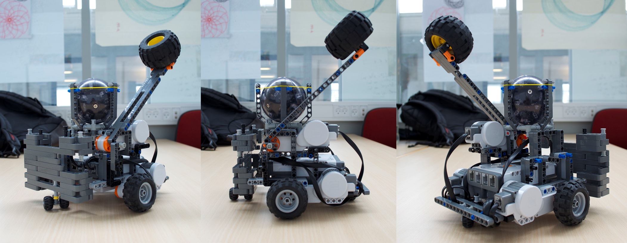
Pictures of the remote controlled robot from different angles.
The only thing left was add the limitation on how far the hitting arm should be able to move into the code. First we added a case to the RCanimal-class’ switch for input from the Bluetooth connection:
1 2 3 4 | case 9: attack = true; break; } |
We implemented a thread that listens for the attack command which plays a punch sound, moves the hitting arm down, waits for a bit and then moves the hitting arm back to its upright position.
1 2 3 4 5 6 7 8 9 10 11 12 13 14 15 16 17 18 19 20 21 22 | class AttackHandling extends Thread { private NXTRegulatedMotor hammer = new NXTRegulatedMotor(MotorPort.A); public AttackHandling() { hammer.setSpeed(hammer.getMaxSpeed()); } public void run() { while (true) { if (attack) { Sound.playSample(new File("punch3.wav")); hammer.rotateTo(100); try { Thread.sleep(500); } catch (InterruptedException e) { e.printStackTrace(); } hammer.rotateTo(0); attack = false; } LCD.drawString("atk: " + attack, 0, 6); } } } |
Complete System
The state of the system at the moment is the following: First off we have constructed and programmed our autonomous robots to move around in the environment, if it’s hungry and it sees “food” it’ll eat it. If the infrared sensor on the autonomous robot sees the infrared ball placed on the robot controlled by the player it’ll turn and move away from it – in essence try to run away from the player. Furthermore if the ultra sonic sensor detects something within a certain distance it’ll turn and move in a different direction to avoid obstacles, which might be another autonomous robot and thus avoid them bumping into each other. The color sensor used to detect “food” is also used when the robot comes near the edge of the environment where there is a color change in the environment from light gray, read by the sensor as white, to dark gray, read by the sensor as black. In that case the robot turns randomly a number of degrees and checks if it’s out of the dark gray area if so it will continue moving forward. Finally for the autonomous robot it will, when hit on top, detected by the touch sensor, stop moving and start playing a sound as well as moving around itself for about eight seconds.
The remote controlled robot does not have any input from any sensor that it can act upon, it can only wait for input from the user via a Bluetooth connection which is established when the system is set up. As is mentioned in a previous blog entry we had some trouble with the keyboard input as we aren’t using a mechanical keyboard and thus not all key-press combinations can be registered by the non-mechanical keyboard. The user input is recorded on a computer which is also responsible for transmitting it via the Bluetooth connection to the robot. The keys used to control robot is W, A, S, D and the spacebar. Furthermore we have mounted a smartphone on the robot to transmit a video feed to the user which is the player’s point of view. We use Skype video call to transmit video as we have found this to be the best solution for the moment being, as explained in End-course project 2[2].
Finally we’ve made a small video for the system in action which can be seen below or at http://youtu.be/0lu5gPSlYVQ

In the video you see the system as a whole, where all the different parts comes together, how the autonomous robots act according to their motivation and the remote controlled robot influences the game. For instance when the remote controlled robot hits one of the autonomous robots on top it will stop and start spinning around itself, or if the IR sensor detect the IR ball the autonomous robots become scared, turn away and “run” from the remote controlled robot. The video also shows the interaction that the player has with the remote controlled robot, and how “up close and personal” he/she has to be in order to hit an autonomous robot.
Lego Digital Designer
We have constructed a model of the remote controlled robot in Lego Digital Designer, available at http://code.bech.in/digital_control/lab16/RCanimal.lxf.
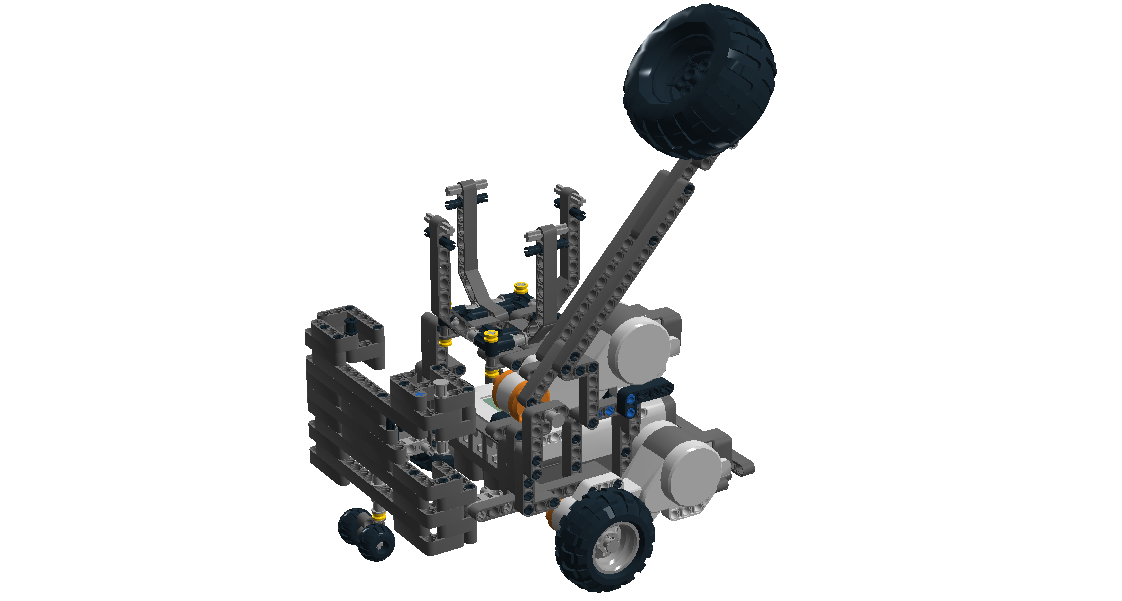
The remote controlled robot constructed in Lego Digital Designer
Final Code
- Robot code
- autAnimal
- motivation
- rcAnimal
- PC code
References
[1] End-course project 1, http://bech.in/?p=427
[2] End-course project 2, http://bech.in/?p=463
[3] Sørensen, Holm and Altheide, Whack-A-Robot – A Behavior Based Game, http://lego.wikidot.com/report:end-course-project-report