Date: 9th of May 2013
Participating group members: Kenneth Baagøe, Morten D. Bech and Thomas Winding
Activity duration: 6 hours
Prelude
For the exam of the course Digital Control we have to make a project based on some of the topics presented during the course.
Goal
The goal of this lab session is to decide on a project we would like to do and describe it in details with regards to hardware, software and possible difficult problems we might able to see now in the project.
Plan
First we will brainstorm some different ideas we can come up with and then select three and describe these in a bit more detail, finally will we select one which we will.
Ideas
Mapping (Inspired by Maja Mataric[1])
Mapping out the layout of a room and navigating it without bumping in to objects that might block the robots path. Might need to be in a fixed environment as a random environment could be too demanding.
RC animal / autonomous animals
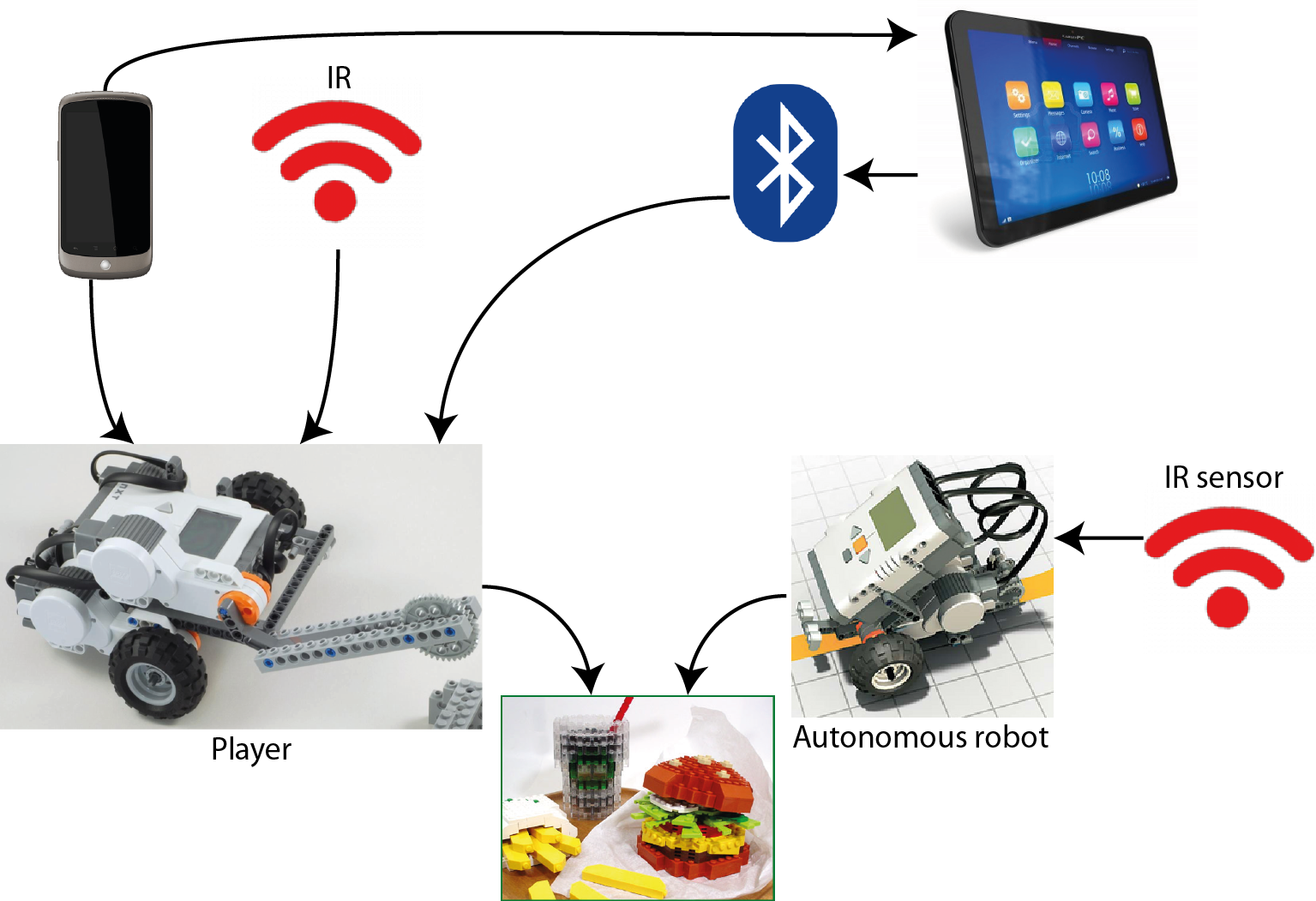
Consists of a single remote controlled “animal” and a number of autonomous “animals”. The autonomous robots try to steal food from the the player (RC animal) while the player incapacitates them to stop them. Additionally the player animal is controlled though a tablet of some sort which also provides a point of view from the animal.
WRO Senior High School Regular Challenge
Work on the challenge and came up with one or a couple of possible designs for a robot that complete the challenge. Also compare software possibilities between NXT-G and LeJOS, because the only software allowed at the international finale is NXT-G. The challenge can be found here.
Flock of robots
A flock of robots that are able to propagate updates to other robots. Basically, if a single robot of the flock receives an update it can then send the update to another robot(s) and they can, in turn, send it to yet another robot.
Zombie robots
Builds on the flock of robots. One robot could get “infected” with a zombie virus and start infecting other robots. The healthy robots try to avoid the zombies.
Evolution/self-learning
A robot that is able to evolve. Could be realized with a line-following PID controller-based robot that would adjust the PID values automatically and compare the run times, thus finding the optimal values for the PID controller. Would probably also need a way to find its way home to the start position in case the PID values throw it off the track.
Soccer/penalty-kick game[2]
A game where the player could control either the robot that would kick the ball and an autonomous robot would act as goalkeeper or vice versa.
Top 3
We have selected following three ideas as our top 3:
- Mapping
- RC animal / autonomous animals
- Zombie robots
An addition that can probably be used in most of our ideas, a holonomic drive allows a robot to drive in all directions without turning, which think could be funny to incorporate. We will present the three ideas in a little more detail and technical perspective.
Mapping
Hardware/physical
For the mapping robot we would need the following hardware:
- One NXT brick
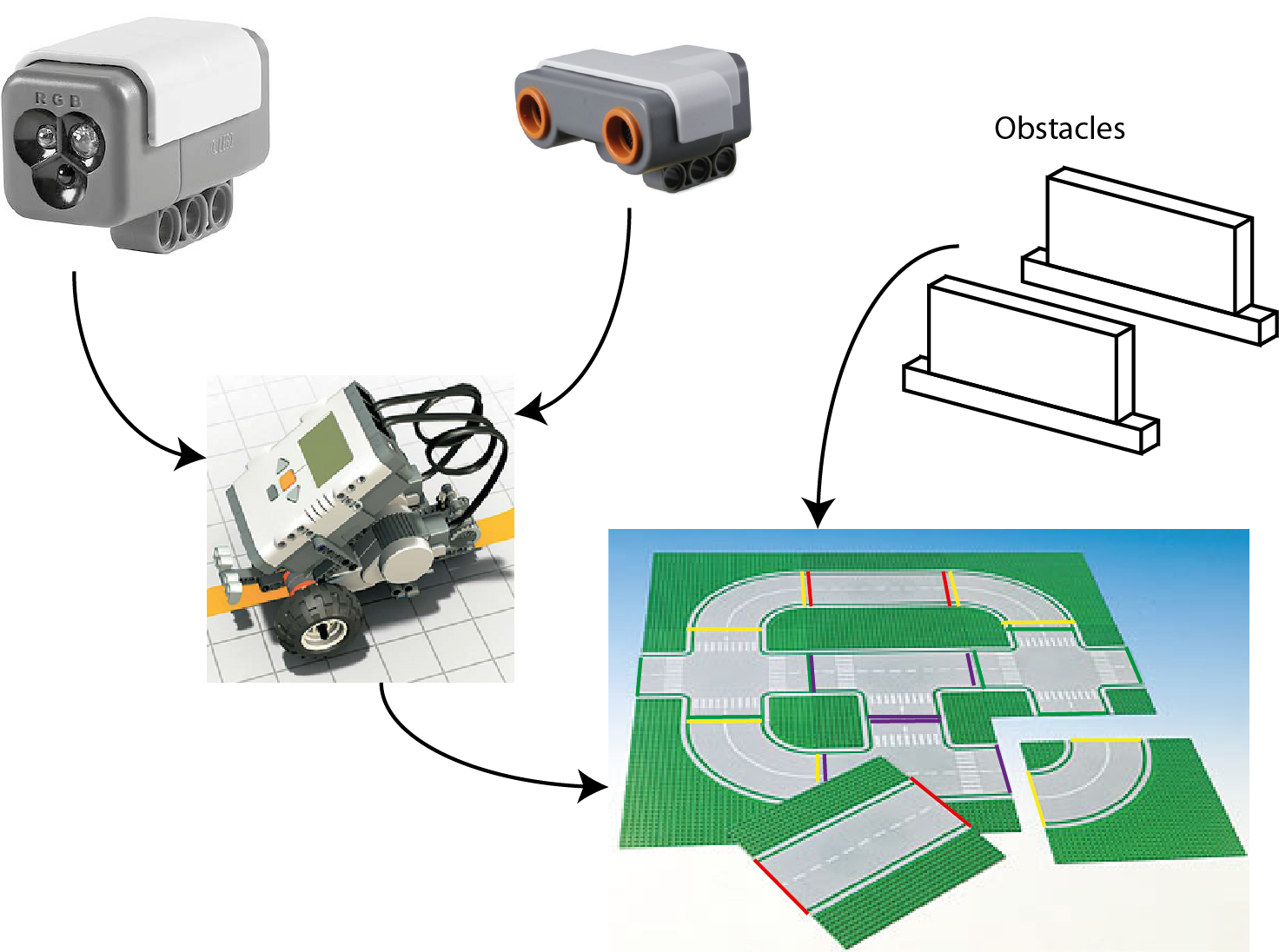
- Sensors for detection (Ultrasonic sensor and color/light sensor)
- Landmarks
- Environment
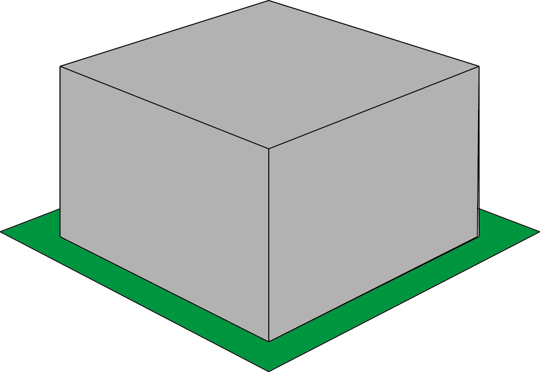
- Movable obstacles
The environment will be a roadlike environment, made up from several squares (see http://legolab.cs.au.dk/DigitalControl.dir/city.jpg for an example), which we can most likely make/print while obstacles can be mostly anything that will block the robot. Landmarks can e.g. be colored lines at the edge of a square so the robot knows when it enters a new square.
Software
On the software side we will use lejOS to program the robot in Java. Controlling the robot will be handled with a Navigator. For an initial run with the robot to discover what the environment looks like we will need some sort of discovery protocol. Furthermore the robot should be able to plan a path that would be the shortest possible when it needs to go somewhere, it should also be able to recalculate a new path if the shortest path is blocked.
Expected difficulties
We believe that the implementation of the planning part of the robot will be somewhat difficult to write.
Expectations
We believe we will be able to fully implement this idea and have the robot working as described in the idea section.
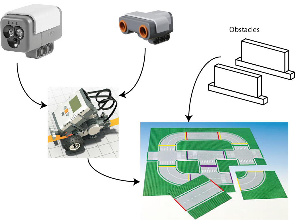
Components need for the Mapping project.
RC animal/autonomous animals
Hardware
1 NXT for the RC robot + an IR emitter.
4 NXT for the animals + IR sensors.
1 laptop/PC/tablet.
1 smartphone.
Environment: We’ll need an arena in which the event will take place. The driver shall not be able to see this though.
Software
We’ll need streaming software for live video stream of the RC-robot(using Skype could be a solution in this particular situation). In able to manage the robot we’ll also have to find/code some protocol(s) that can be used. Motivation based animals.
Expected difficulties
It will be a challenge creating a low-latency live video stream, and we might have to create some sort of overlay using Skype instead of start coding from scratch. Furthermore the latency from the controller(laptop/PC/tablet) to the NXT we will consider as a challenge.
Expectations
We’re expecting the robot to be controlled remotely but not necessarily controlled from a tablet. We also expect the animals to have a behavior based “mind”.
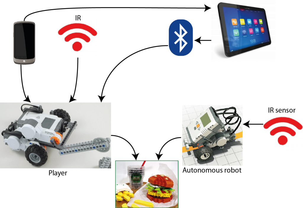
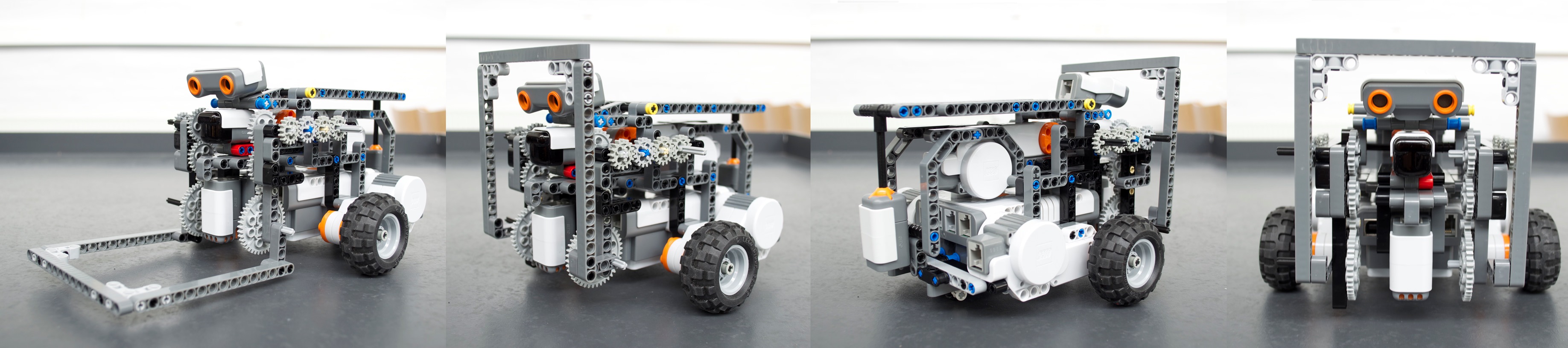
Components need for the RC animal project.
Attack of the Zombies!
As explained earlier the a group of robots “live” in some environment where one of the robots gets infected by an virus and now tries to infect the other robots. We imagine that the environment is some flat surface surround by a wall to keep the robots in a confined space. Therefore the robots must have some way of sensing the wall. As what makes a robot a infected robot and how does it infect other robots? One solution is mount an IR-emitter and an IR-sensor on all the robot, the infected once will turn on their emitter which gives the not infected ones a chance to survive. The placement of the IR-sensor then becomes crucial, is it place as on mammal or predator? Furthermore how does a zombie infect another robot? It could be done is several ways, one it to communicate it through bluetooth every time a robot hits another robot, but this might also conflict with the wall detection.
Hardware
For this project we are going to need approx. 5 robots, a flat surface with an edge around it, same number of IR-emitter and IR-sensors as robots. The IR-emitter could be something we constructed our self which include some LEDs as well to indicate towards the viewer which robot are infected and which aren’t.
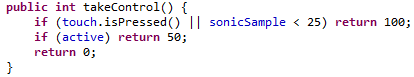
Software
The software is going to need two states that it can change between, it might be implemented as a Strategy pattern or as a simply simple state object. Also we need some implementation of change from one state to other and back again for resetting, which could be done via BlueTooth. Also we need to be able to infect the first Zombie. Finally the software of the for the not infect could be motivation based.
Expected difficulties
One of the concerns we have for this project is how we indicate that a robot is infected, both to the other robots and the viewer, if we were to construct our own emitter we could take up a lot of time. Secondly we are concerned about the rate that the infection happens with, we don’t want the rate to be too fast nor too slow, because we don’t want it to be too borrowing nor over too fast.
Expectations
We expect that we would be able to complete the project in its full, but if can the infection rate perfect is another question.

Components need for the Attack of the Zombie project
And the winner is
We have selected RC aminal as the project we would like to do for our end-course project, however we wouldn’t commit to it 100% until we have had a chance to talk to Ole. Our reason for selecting that one is that we found the most fun to do of the three, while all could be interesting to do. Furthermore we have made a small timetable which can be seen be below.
Timetable
So fare we have come up with the following timetable for the project:
| Tuesday, 14th of May |
Talk to Ole regarding our choice of project |
| Thursday, 16th of May |
Correct project depend on feedback we get from Ole, work on a remote controlled robot. |
| Tuesday, 21st of May |
Complete the remote control if not already done. |
| Thursday, 23rd of May |
Construction of environment and robots. |
References
[1] Maja J. Mataric, Integration of Representation Into Goal-Driven Behavior-Based Robots, in IEEE Transactions on Robotics and Automation, 8(3), Jun 1992, 304-312.
[2] World Robot Olympiad Gen II Football, http://wro2013.org/challenges/challenges-football